Compact mobile oil recycling system

a mobile oil recycling and mobile technology, applied in the direction of moving filter element filters, filtration separation, separation processes, etc., can solve the problems of engine oil contamination, high flow requirements, and contribute to engine wear and tear

Inactive Publication Date: 2002-04-09
DE SYLVA ROBERT F
View PDF14 Cites 26 Cited by
  • Summary
  • Abstract
  • Description
  • Claims
  • Application Information

AI Technical Summary

Problems solved by technology

Engine oil is contaminated by gases from engine cylinder blow-by; by solids from engine component wear, and by liquids from coolant leeks and condensed blow-by gasses.
High flow requirements limit the ability of conventional full flow filters to remove very small solid contaminants.
Large particles of twenty microns or larger often pass through such filters and contribute to engine wear.
In addition, conventional full flow filters are ineffective at removing liquid contaminants from the oil.
These oil refining systems may obviate the need for interval oil changes but require interval filter changes.
The systems require a large evaporation compartment and an expensive electric heating element.
The heating element increases the risk of the systems exploding due to gas ignition.
The large size of the systems limits installation to large trucks and automobiles with ample space.
Installation on most modern automobiles is difficult and expensive due to limited space.
In addition, electrical connections required for the electric heating elements complicate installation, and decrease the reliability of the systems.
Public acceptance of the systems has been minimal as a result of these problems.

Method used


Image

  • Compact mobile oil recycling system
  • Compact mobile oil recycling system
  • Compact mobile oil recycling system

Examples


embodiment 100

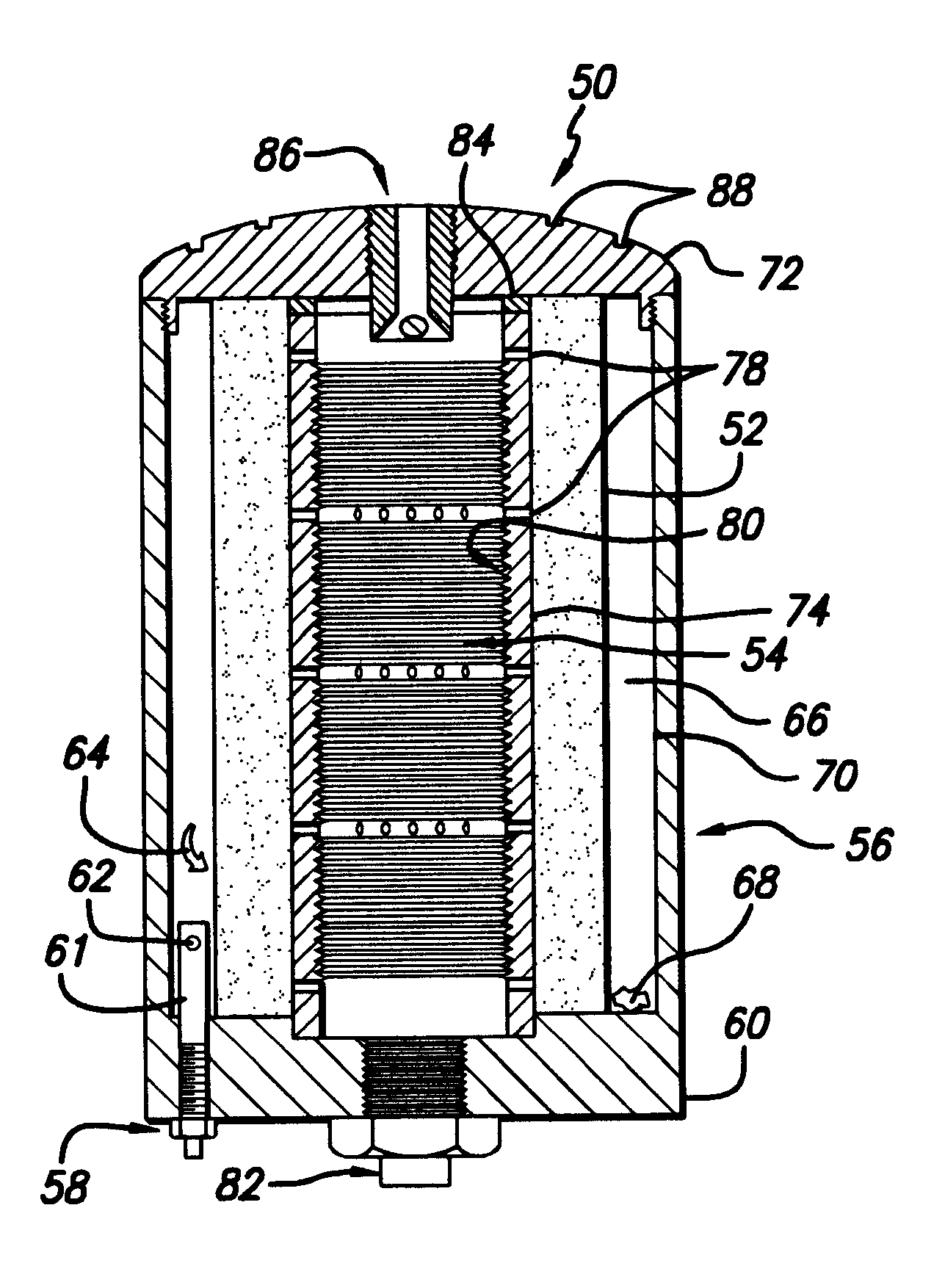
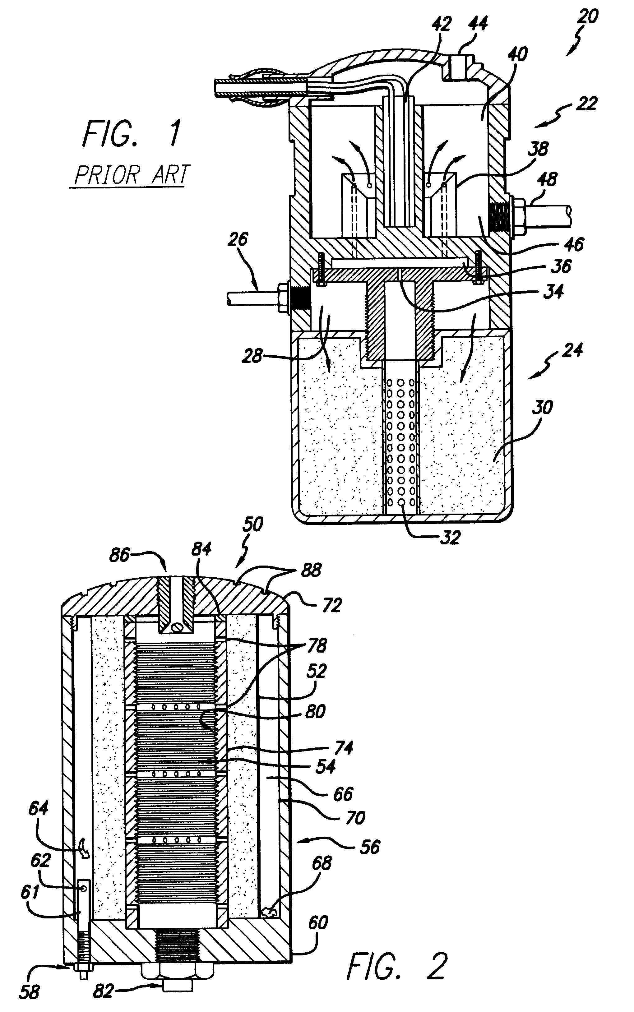
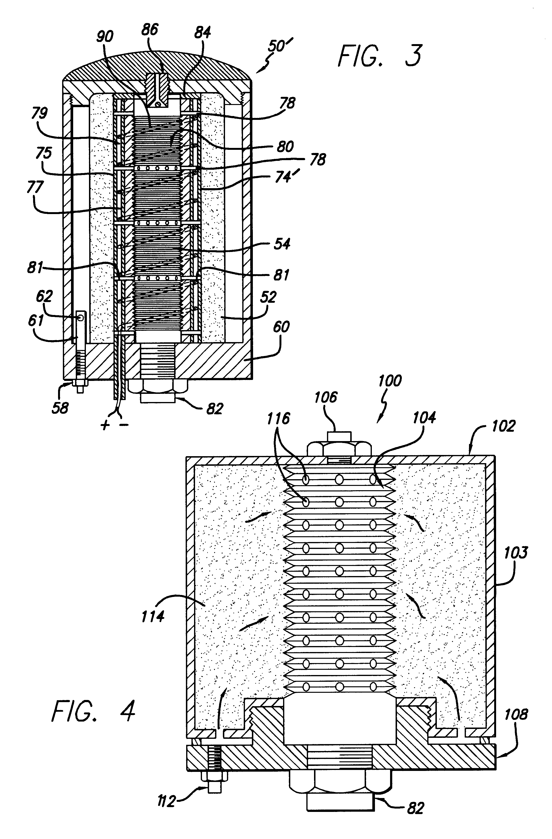
FIG. 4 is a cross-sectional view of an alternative embodiment 100 of the present invention including a spin-on filter 102 having a spin-on filter canister 103. The filter 102 is a filter of conventional design with the exception that the filter 102 includes a special interior surface 104 and a vapor vent 106.

The filter 102 is screwed onto a base plate 108 that includes an oil outlet 82 and an oil inlet 112. Pressurized oil from an engine (not shown) enters the filter 102 through a base plate 108. Oil passes through a filtering element 114 included in the filter 102, where solid contaminants are removed, and some liquid contaminants are absorbed and / or neutralized. The pressurized oil, free of solid contaminants, is released to atmospheric pressure as it passes through the special surface 104 via small holes 116. The holes 116 are drilled sufficiently small to prevent oil from backing up inside the filter 102. This change in pressure facilitates vaporization of liquid contaminants an...

embodiment 120

FIG. 5 is a cross-sectional view of an illustrative embodiment 120 of the present invention adapted for use with a conventional spin-on filter 122. The illustrative embodiment 120 includes a plate 124 and an evaporation attachment 126. The attachment 126 is a tube having a textured inside surface 128 with holes 130 and is screwed into the plate 124. Oil cleaned by the filter 102 may flow through the holes 130 and over a top 132 of the evaporation attachment 126. Those skilled in the art will appreciate that oil flow may be prevented from flowing over the top 132 without departing from the scope of the present invention.

The operation of the illustrative embodiment 120 is analogous to the operation of the alternative embodiment of FIG. 4 with the exception that vapors vaporized from the surface 128 may exit through the plate 124 instead of the top of the filter 120. The plate 124 has a vapor outlet 134. A vapor tube 136 extends from the vapor outlet 134 and opens into the evaporation ...

embodiment 150

FIG. 6 is a cross-sectional view of a second alternative embodiment 150 of the present invention. The system 150 includes a filter 152 surrounded by an expanded evaporation surface 156.

Heated, pressurized oil enters the system 50 via an oil inlet 112'. Oil flows through the filter 152 and onto the evaporation surface 156 via the small holes 116'. Oil passing through the holes 116' is released to atmospheric pressure, facilitating the vaporization of contaminants from the oil on the surface 156. Vapors are vented through a vent hole 158 in a cap 157 and clean oil drains back to the engine (not shown) via an oil outlet 82.

A groove 160 varies in depth around the circumference of the system 50, helping to direct oil to the oil outlet 82, and preventing oil coagulation in the groove 160.


PUM

PropertyMeasurementUnit
diameteraaaaaaaaaa
sizeaaaaaaaaaa
pressureaaaaaaaaaa

Abstract

A mobile oil recycling system adapted for use with an oil-lubricated combustion engine. The inventive system includes an evaporation chamber for changing the pressure of the oil from a first pressure to a second pressure lower than the first pressure. Metering holes in a textured three-dimensional evaporation surface at the second pressure allow oil to spread over the three-dimensional surface area and evaporate contaminants from the oil. In a specific embodiment, the system further includes a filtering system for removing solid contaminants from the oil. A housing contains and supports the filtering system and the contaminant removal chamber, and directs the flow of oil through the recycling system. In a more specific embodiment the housing includes a base having an oil inlet for allowing pressurized oil to enter the oil recycling system and an oil outlet for allowing oil at atmospheric pressure to exit the recycling system. The three-dimensional evaporation surface has channels or grooves therein and is located in the liquid and gas contaminant removal chamber. A vent in the housing allows vaporized contaminants to escape from the chamber. The unique three-dimensional surface of the present invention obviates the need for an electric heater element, and eliminates wasted space and excess weight inherent in systems that have evaporation units stacked on filters.

Description

1. Field of InventionThis invention relates to oil recycling devices. Specifically, the present invention relates to devices for maintaining clean engine oil while an engine is operating.2. Description of the Related ArtOil is a lubricant in a variety of applications ranging from electric generators to printing presses to automobiles. Such applications require clean oil with minimal liquid, gas, and solid contaminants.Typical engine oil contains a variety of solid, gas, and liquid contaminants. Engine oil is contaminated by gases from engine cylinder blow-by; by solids from engine component wear, and by liquids from coolant leeks and condensed blow-by gasses. Liquids combine with sulfur and other compounds from cylinder blow-by, creating corrosive acids, such as sulfuric acid. These contaminants corrode engine parts and deplete special minerals and detergents added to help maintain important oil properties including lubricity and viscosity.To reduce problems associated with oil cont...

Claims


Application Information

Patent Timeline
Patent Type & Authority Patents(United States)
IPC IPC(8): B01D36/00B01D29/15B01D24/04B01D24/02B01D24/08B01D29/13B01D35/14B01D35/157
CPCB01D24/04B01D24/08B01D29/15B01D35/157B01D35/1576B01D36/001B01D29/908B01D35/185B01D2201/0415
Inventor DE SYLVA, ROBERT F.
Owner DE SYLVA ROBERT F
Why Eureka
Try Eureka