Hot stand-by switching apparatus

a technology of hot standby switching and switching apparatus, which is applied in the direction of transmission, relays, transportation and packaging, etc., can solve the problems of long time required for switching, poor reliability of conventional hot standby switching apparatuses, and high cost of rf power switching devices

Inactive Publication Date: 2002-04-09
NEC CORP
View PDF13 Cites 41 Cited by
  • Summary
  • Abstract
  • Description
  • Claims
  • Application Information

AI Technical Summary

Problems solved by technology

However, the switching devices for RF power are expensive.
Further, the conventional hot-stand-by switching apparatuses as mentioned above are poor in reliability, because only one switching device is employed commonly for both of the active and preparative circuits.
Furthermore, the time required...

Method used


Image

  • Hot stand-by switching apparatus
  • Hot stand-by switching apparatus
  • Hot stand-by switching apparatus

Examples


Embodiment Construction

Preferred embodiment of the present invention is explained, referring to the drawings.

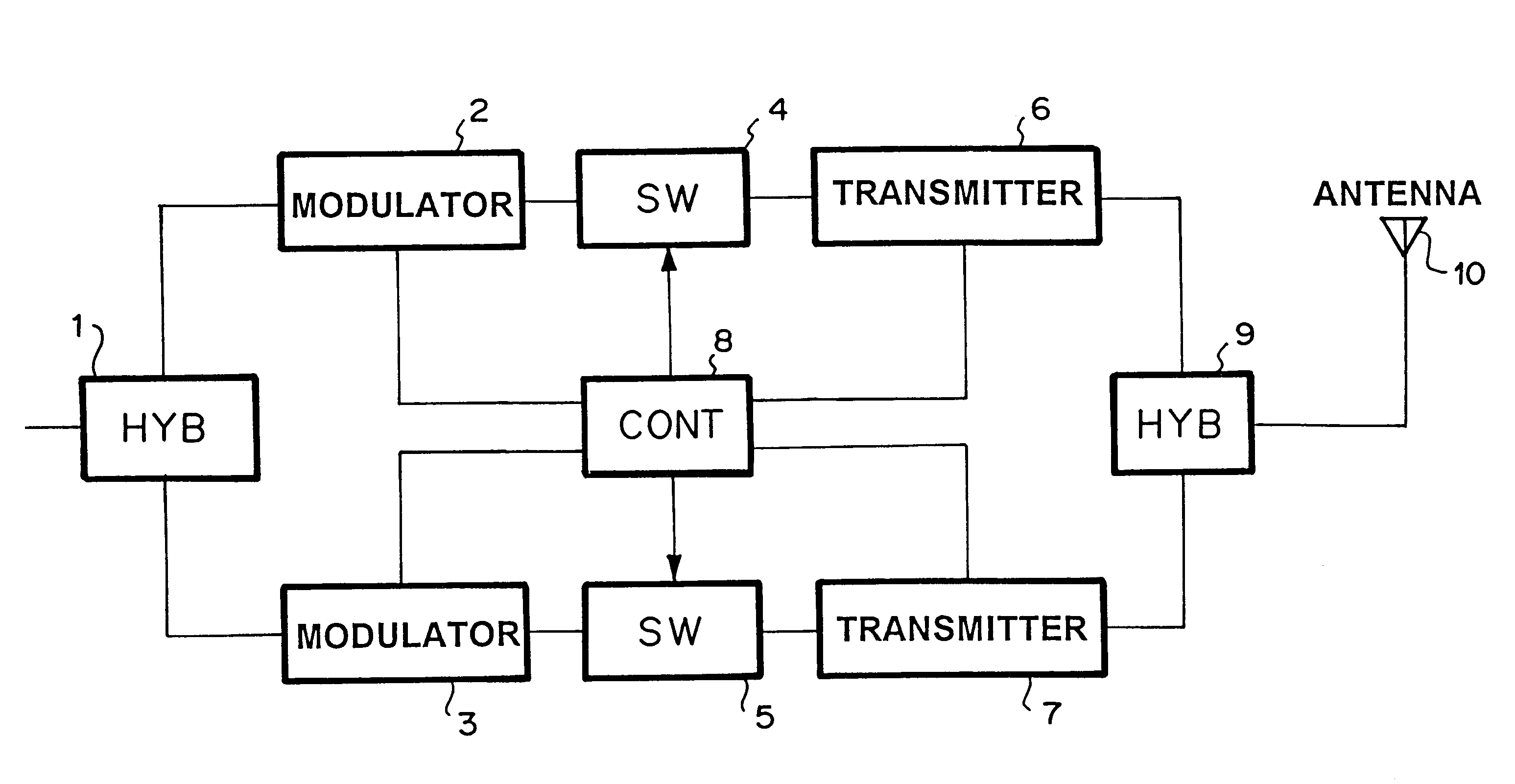
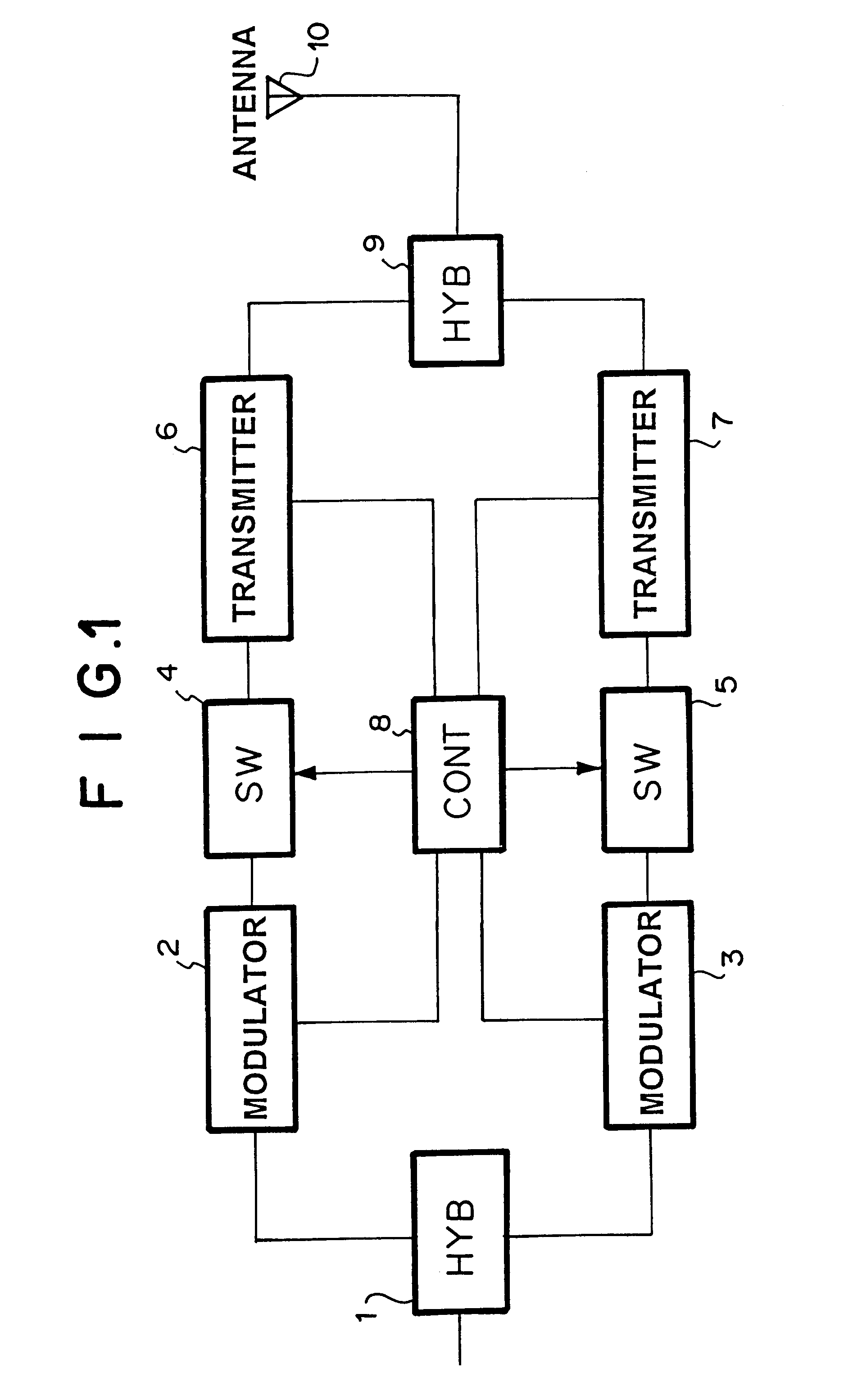
A block diagram of the hot stand-by switching apparatus of the present invention is shown in FIG. 1. As shown in FIG. 1, the input signal is branched into two signals by distributor (HYB) 1. One of the branched signals is modulated by modulator 2, is inputted into switch (SW) 4, and amplified by transmitter 6, while another branched signal is modulated by modulator 3, is inputted into switch (SW) 5, and amplified by transmitter 7. Further, the outputs from transmitters 6 and 7 are inputted into coupler (HYB) 9 which is connected with antenna 10.

Controller (CONT) 8 controls SW 4 and SW 5 on the basis of the outputs from modulators 2 and 3 and transmitters 6 and 7.

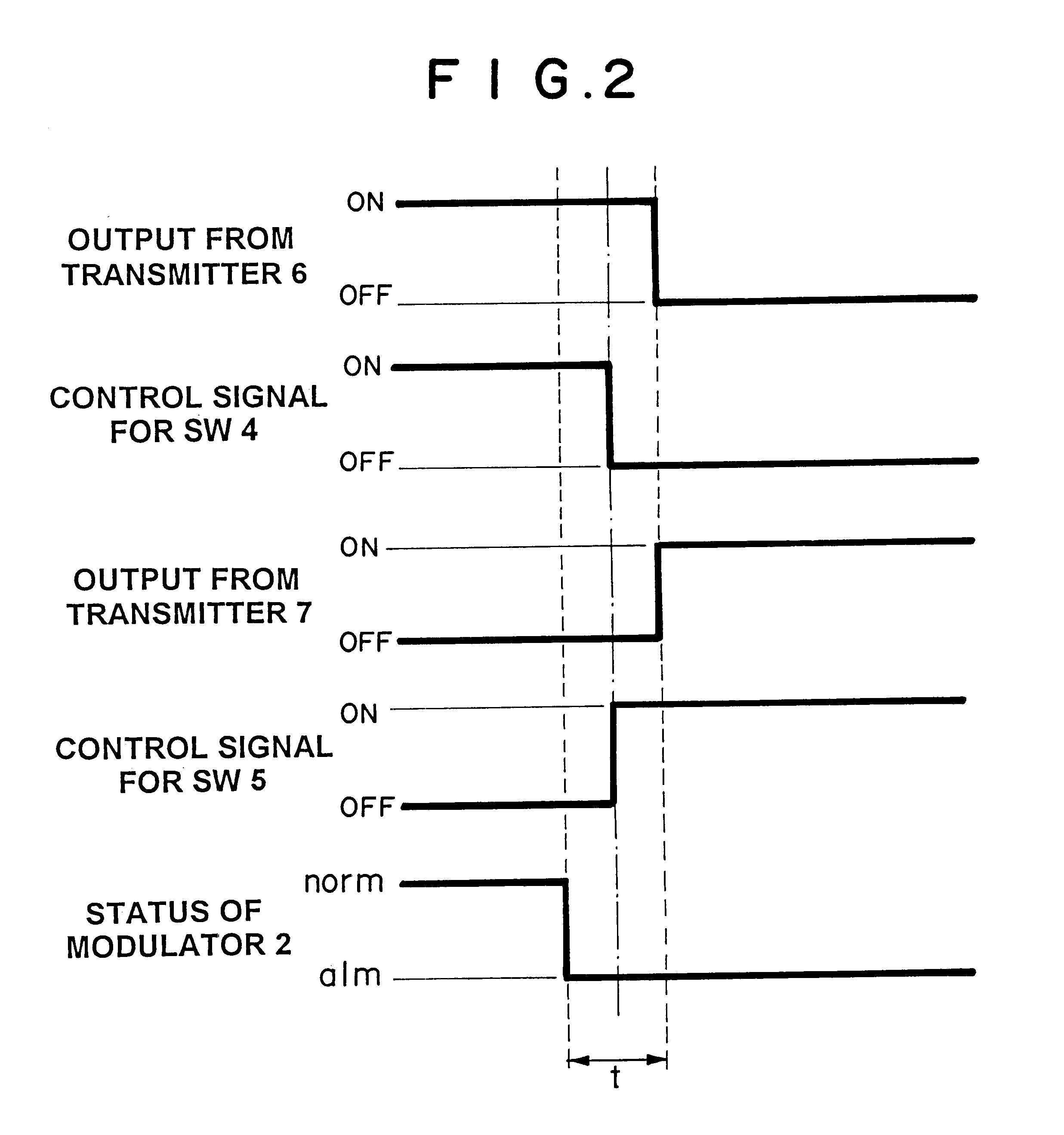
A time chart for explaining the operation of the hot stand-by switching apparatus of the present invention is illustrated in FIG. 2. It is assumed that the active circuit comprises modulator 2, SW 4, and transmitter 6, while the preparative...


PUM


Abstract

To provide a hot stand-by switching apparatus which is cheaper and more reliable than a conventional RF power switching device. Further, Output level and frequencies during rise and fall times are stabilized. The hot stand-by apparatus of the present invention comprises coupler for outputting either the active signal or the preparative signal, active and preparative transmitters, and switches which are connected with the input terminals of transmitters, respectively.

Description

1. Technical Field of the InventionThe present invention relates to a hot stand-by switching apparatus which comprises a signal output means for outputting an active signal, or a preparative signal, and switches connected with the input terminals of an active transmitter and a preparative transmitter, respectively.2. Description of the Prior ArtConventionally, switching means for replacing an active power amplifier by an preparative power amplifier are connected with the output terminals of these amplifiers, as disclosed, for example, in JP 9-331275 A (1997).Further, one of the conventional hot stand-by switching apparatus as disclosed in JP 3-270515 A (1991) comprises a directional coupler, wherein local oscillators, power sources for the local oscillators, and variable attenuators for transmitters are controlled.However, the switching devices for RF power are expensive. Further, the conventional hot-stand-by switching apparatuses as mentioned above are poor in reliability, because...

Claims


Application Information

Patent Timeline
IPC IPC(8): H04B1/74H04L69/40
CPCH04B1/74
Inventor NORO, ATSUSHI
Owner NEC CORP
Why Eureka
Try Eureka