Closed-loop independent DLL-controlled rise/fall time control circuit

a control circuit and closed-loop technology, applied in the direction of oscillator generators, pulse manipulation, pulse techniques, etc., can solve problems such as timing failures, adversely affecting system performance, and signal integrity and reliability problems,

Active Publication Date: 2006-05-02
TAHOE RES LTD
View PDF13 Cites 28 Cited by
  • Summary
  • Abstract
  • Description
  • Claims
  • Application Information

AI Technical Summary

Problems solved by technology

If left unaddressed, these variations will adversely affect system performance.
For example, if the rise / fall time is too slow, timing failures are likely to occur.
Conversely, if the rise / fall time is too fast, signal integrity and reliability problems may arise because of large reflections and over / undershoot effects.
The methods described above suffer from a number of drawbacks.
For example, both methods take an indirect approach to controlling rise / fall times that is considered to be slow and inefficient.
This can lead to poor edge rates, even in cases where the compensation circuit works properly.

Method used


Image

  • Closed-loop independent DLL-controlled rise/fall time control circuit
  • Closed-loop independent DLL-controlled rise/fall time control circuit
  • Closed-loop independent DLL-controlled rise/fall time control circuit

Examples


Embodiment Construction

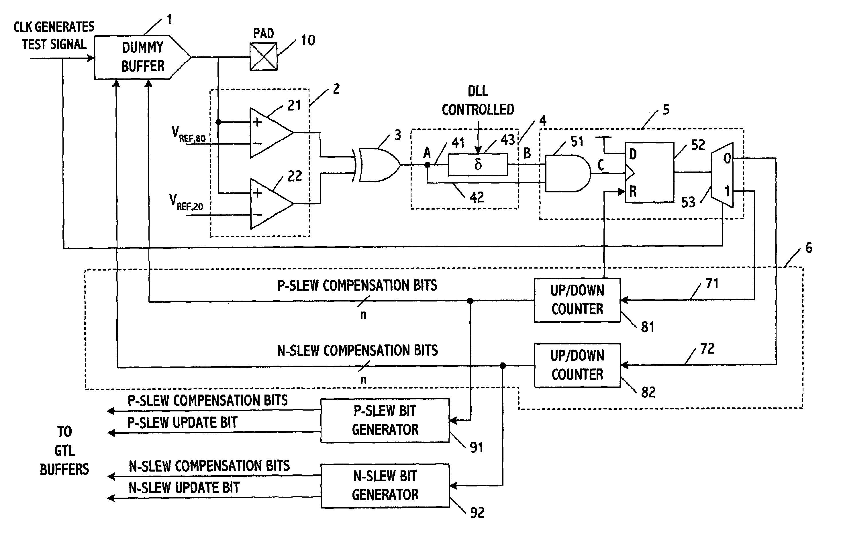
[0015]FIG. 1 shows a circuit for controlling the rise and / or fall time of driving signals in accordance with one embodiment of the present invention. The driving signals may be any type including but not limited to I / O signals traveling between a CPU and chipset on the motherboard of a computer or other processing system, or ones traveling along chipset / DRAM connections. While the embodiments described herein are ideal for use in controlling high-speed I / O signals, other embodiments may control the rise / fall times of moderately fast signals such as those operating in association with JTAG / ITP ports.

[0016]The control circuit includes a dummy buffer 1, a sampling circuit 2, a logic gate 3, a delay circuit 4, a glitch detector 5, and a feedback circuit 6 coupled to the dummy buffer. The dummy buffer generates signals for calibrating the rise / fall times at a signal pad 10, which, for example, may be connected to a power supply on the motherboard. The dummy buffer is preferably an exact ...


PUM


Abstract

A system and method for processing signals determines rise and fall times of a driving signal, compares the rise and fall times to desired values, and independently controls the rise and fall times to equal the desired values. The rise and fall times may be controlled by generating one or more first correction bits based on a difference between the rise time and a corresponding one of the desired values, generating one or more second correction bits based on a difference between the fall time and a corresponding one of the desired values, and then separately applying the bits to independently control the rise and fall times of the driving signal. The driving signal may be an I / O signal or another type of signal.

Description

FIELD[0001]This invention relates to control circuits and methods for generating timing signals.BACKGROUND OF THE INVENTION[0002]The rise / fall time of signals traveling between a CPU and chipset will often vary because of one or more external influences. These influences include variations in silicon strength caused by process, voltage and / or temperature conditions that exist across large numbers of dies. Uncompensated-for changes in supply voltage also contribute to rise / fall time variations. If left unaddressed, these variations will adversely affect system performance. For example, if the rise / fall time is too slow, timing failures are likely to occur. Conversely, if the rise / fall time is too fast, signal integrity and reliability problems may arise because of large reflections and over / undershoot effects.[0003]Various methods have been proposed for controlling the rise / fall times of I / O driving signals on the motherboard of a computer. One method involves matching the strength o...

Claims


Application Information

Patent Timeline
Patent Type & Authority Patents(United States)
IPC IPC(8): H03K5/12H03K3/017H03K5/00H03K5/01
CPCH03K5/01H03K2005/00039
Inventor WILSON, TIMOTHY MRIFANI, MICHAEL C.KIM, SONGMINTAYLOR, GREG
Owner TAHOE RES LTD
Why Eureka
Try Eureka