Water leak detection and correction device

a technology of water leak detection and correction device, which is applied in the direction of instruments, textiles and paper, other washing machines, etc., can solve the problems of unrestricted water surge, damage to the surrounding environment and the appliance, and flooding of the hous

Inactive Publication Date: 2002-04-09
ONSITE PRO
View PDF19 Cites 96 Cited by
  • Summary
  • Abstract
  • Description
  • Claims
  • Application Information

AI Technical Summary

Benefits of technology

The sensor 26 can be constructed to form a closed circuit when a conductive liquid contacts the surface of the sensor 26. Preferably, the sensor 26 is located proximate a water connection or hose. In this position, the sensor 26 is most likely to be contacted by leaking water. As described above, any contact with water acts to close a circuit, which will be described below. When the circuit is closed, an alarm can be activated and / or the emergency valves can be actuated to stop the flow of water to or from the appliance 38. In one arrangement, the sensor is a tin-lead or zinc coated copper device well known to those of ordinary skill in the relevant arts. Of course, other types of sensors that could be used with certain other features, aspects and advantages of the present invention also are well-known.

Problems solved by technology

Such household flooding can be caused by bursting pipes or malfunctioning appliances, for instance.
The resultant flooding often causes damage to the surrounding environment as well as to the appliance itself
However, unless the manually operated shut-off valves, which are typically positioned at the wall behind most washing machines, are closed, water can surge unrestricted through a burst supply hose or can spill from the tank of the malfunctioning washing machine.
Clearly, in an unmonitored situation, the flow of water will rapidly exceed the storage capacity of a catch basin and also can exceed the capacity of a drain positioned within the catch basin.
In addition, toilets can be a source of flooding as well.
Generally, toilets include both a float valve and a seal that stops the flow of water into the toilet; however, if the drain line becomes plugged, or if the float valve or seal malfunctions, water can spill from within the toilet bowl or refill tank onto the floor.
In addition, the supply line can become loosened or can fail.
Thus, large amounts of water can flood a bathroom if the condition remains unmonitored.

Method used


Image

  • Water leak detection and correction device
  • Water leak detection and correction device
  • Water leak detection and correction device

Examples


Embodiment Construction

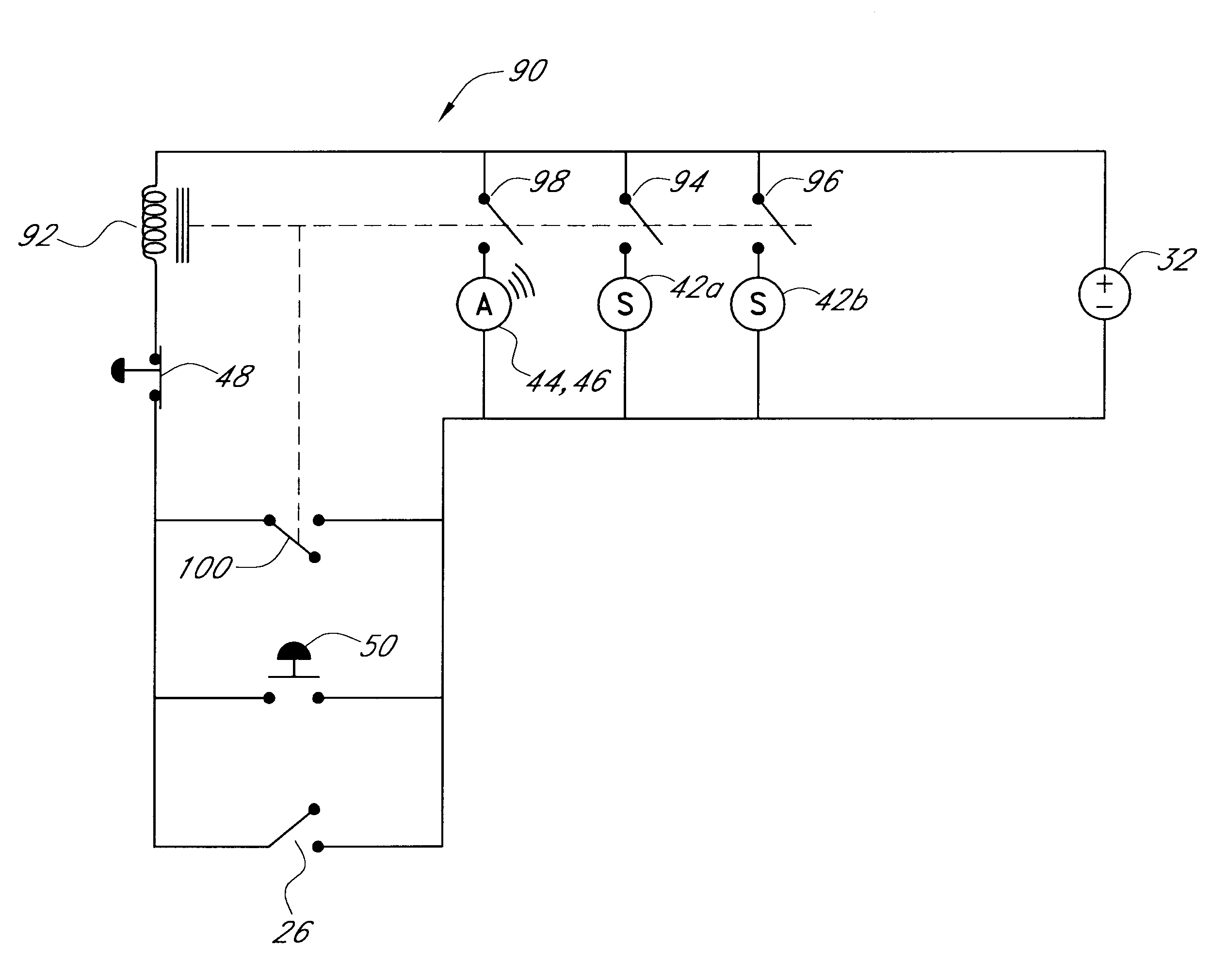
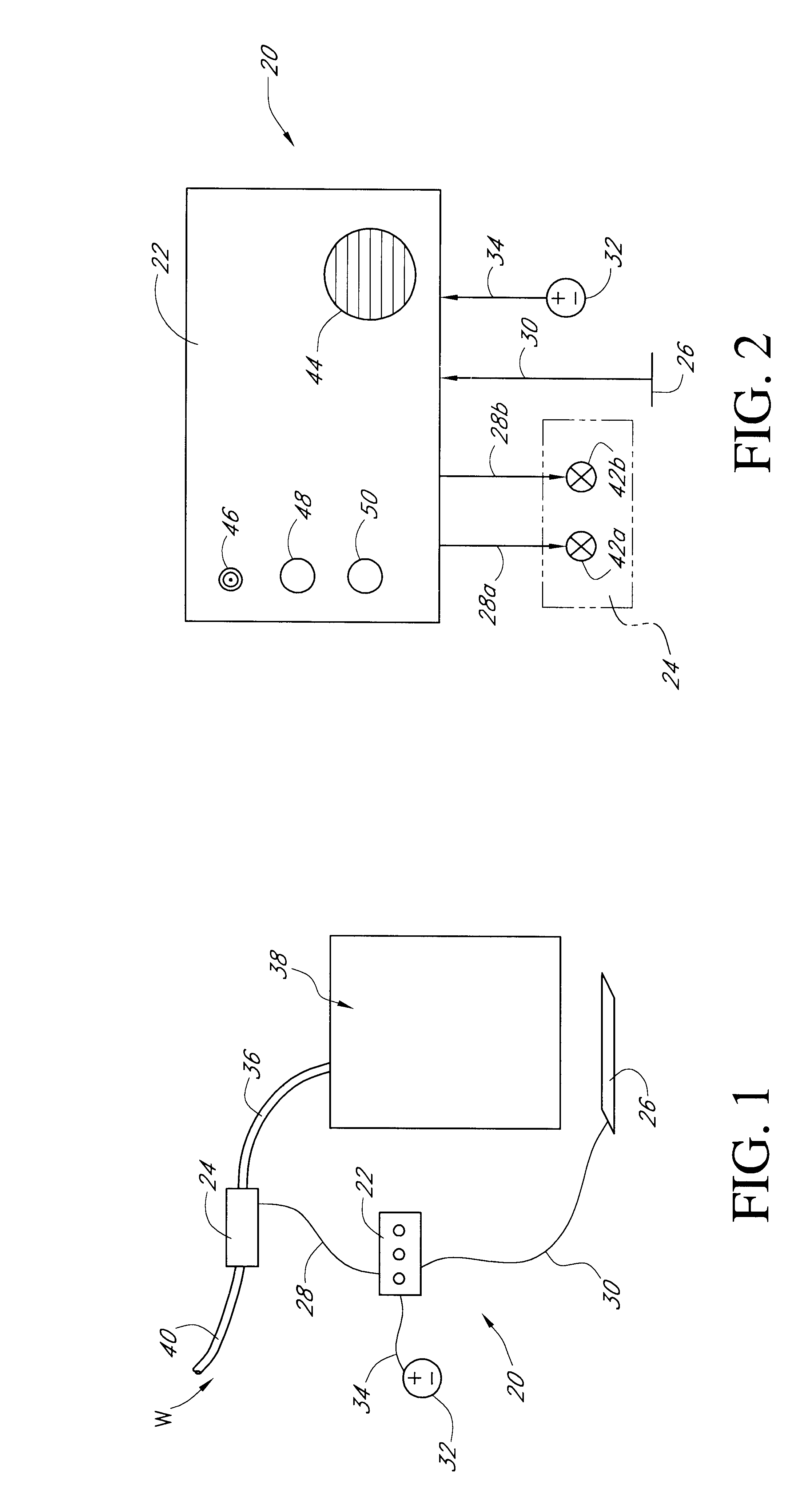
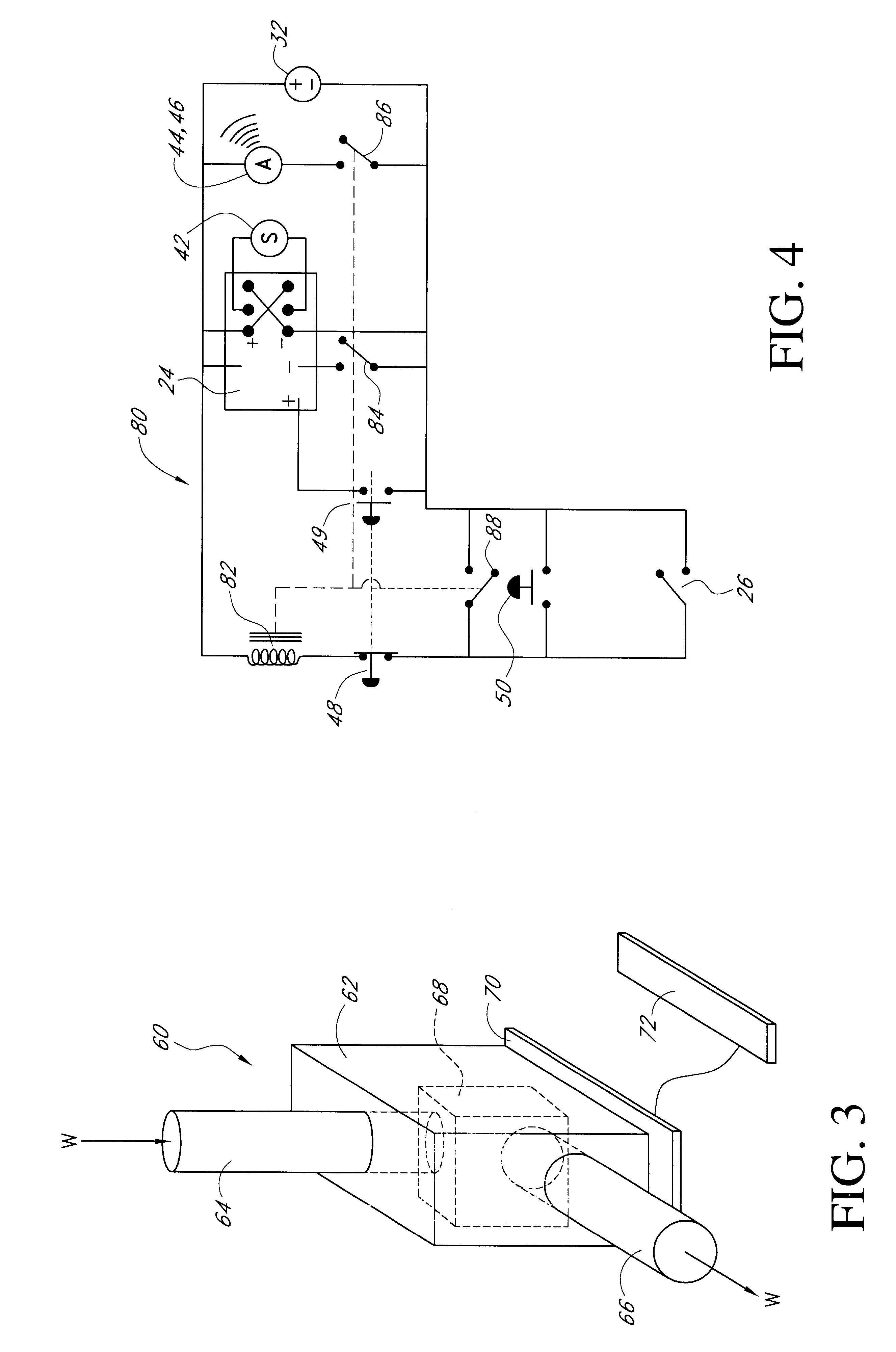
With reference now to FIG. 1, a schematic diagram of a leak detection and restriction apparatus having certain features, aspects and advantages in accordance with the present invention is illustrated. The apparatus, indicated generally by the reference numeral 20, is used to detect leaks and to take corrective action in the event of leaks. As illustrated, the apparatus 20 generally is designed for everyday household use; however, it should be readily apparent to those having ordinary skill in the relevant arts that the apparatus 20 can be used in a variety of other environments. In addition, the apparatus 20 can be modified to detect other types of leaks, such as leaks comprising gases and / or liquids other than water, for example.

In the illustrated arrangement, the apparatus generally comprises a control module 22 that communicates with a valve module 24 and a sensor 26. The control module 22 preferably is electrically connected to the valve module 24 through an electrical signal wi...


PUM


Abstract

A water leak detection apparatus comprises a sensor, a control unit and a valve module. The sensor is adapted to be placed below a water line or coupling. The valve module is positioned as far upstream on a water line as possible. The control unit actuates the valve module and an audible alarm when the sensor detects a water leak. The valve module closes a valve positioned along the water line to restrict flow through the water line until the control unit has been manually reset. The control unit also features a trigger button to allow the valve to be manually cycled for cleaning, for instance.

Description

1. Field of the InventionThe present invention generally relates to systems designed to detect water leaks. More specifically, the present invention relates to systems designed to shut off a water supply to individual appliances if water leaks are detected.2. Related ArtHousehold flooding costs homeowners and insurance companies more than $100 million every year in the United States alone. Such household flooding can be caused by bursting pipes or malfunctioning appliances, for instance. The resultant flooding often causes damage to the surrounding environment as well as to the appliance itselfFor example, flooding of laundry rooms is such a common occurrence that many housing codes now require washing machines to be positioned within catch basins. Thus, when the inevitable overflow occurs, it is hoped that the water will be contained within the catch basins and that the water will not flow into other regions of the laundry rooms. However, unless the manually operated shut-off valve...

Claims


Application Information

Patent Timeline
Patent Type & Authority Patents(United States)
IPC IPC(8): D06F39/08D06F33/47
CPCD06F39/081D06F2105/60D06F33/47
Inventor WALTER, SCOTT A.
Owner ONSITE PRO
Why Eureka
Try Eureka