Multiple signaling mouse with faceted surfaces

a signaling mouse and multi-directional technology, applied in the field of multi-directional mouse with faceted surfaces, can solve the problems of negative ergonomic loss, "click" keys to the mouse are not qualitative improvements,

Inactive Publication Date: 2002-04-09
MAYNARD JR STUART TYRUS
View PDF10 Cites 68 Cited by
  • Summary
  • Abstract
  • Description
  • Claims
  • Application Information

AI Technical Summary

Benefits of technology

It is the intent of the invention to provide additional signals from a single mouse held continuously in a single hand of a user; these signals used to alter the status of a software and cursor operation, and particularly for ease of control of toggled choices within a software, these controls having been heretofor limited to:

Problems solved by technology

Such addition of "click" keys to a mouse is not a qualitative improvement and it has a downside ergonomic loss, as the user must search with fingers for the vital tactile reference points of additional keys.

Method used


Image

  • Multiple signaling mouse with faceted surfaces
  • Multiple signaling mouse with faceted surfaces
  • Multiple signaling mouse with faceted surfaces

Examples


Embodiment Construction

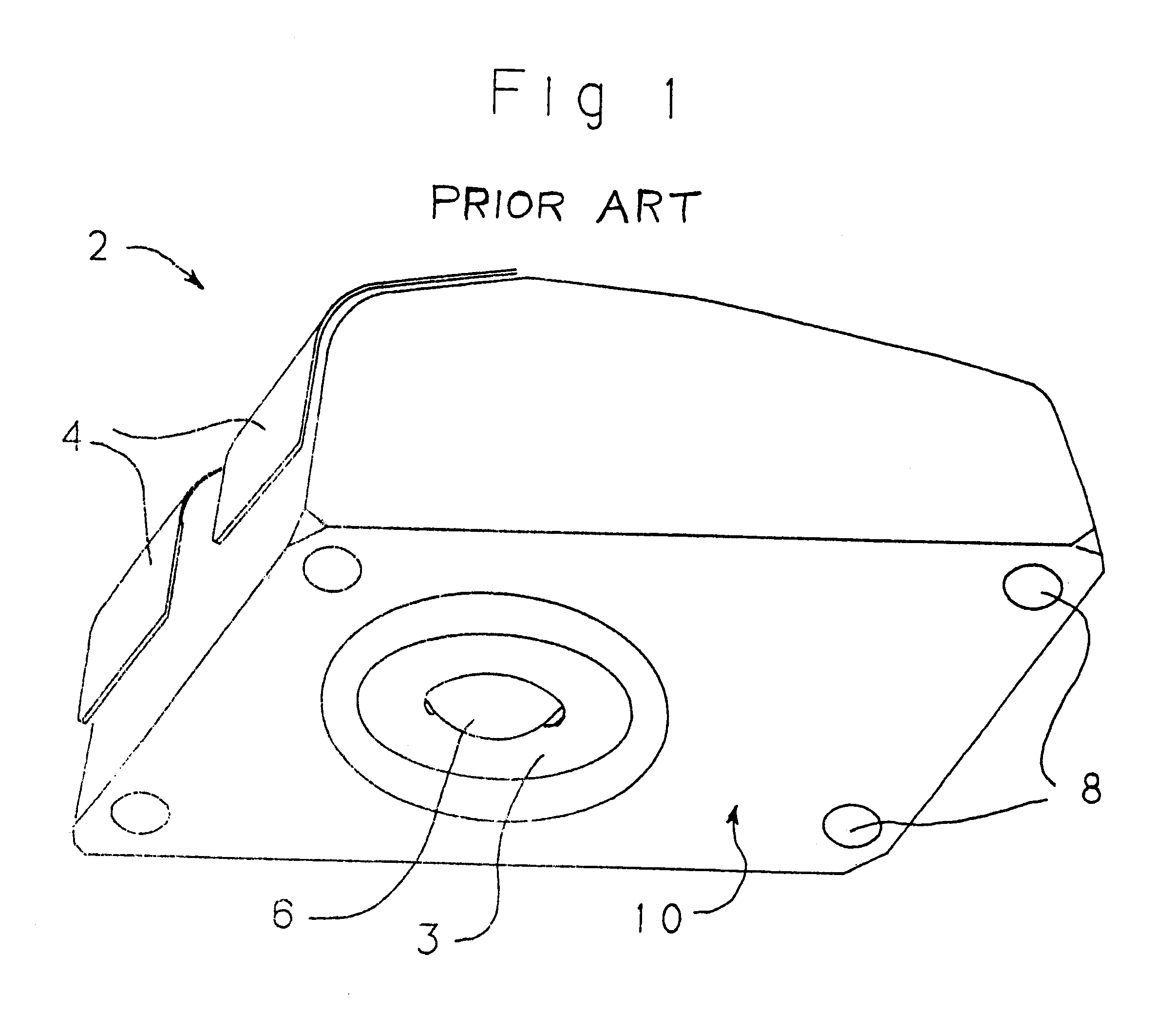
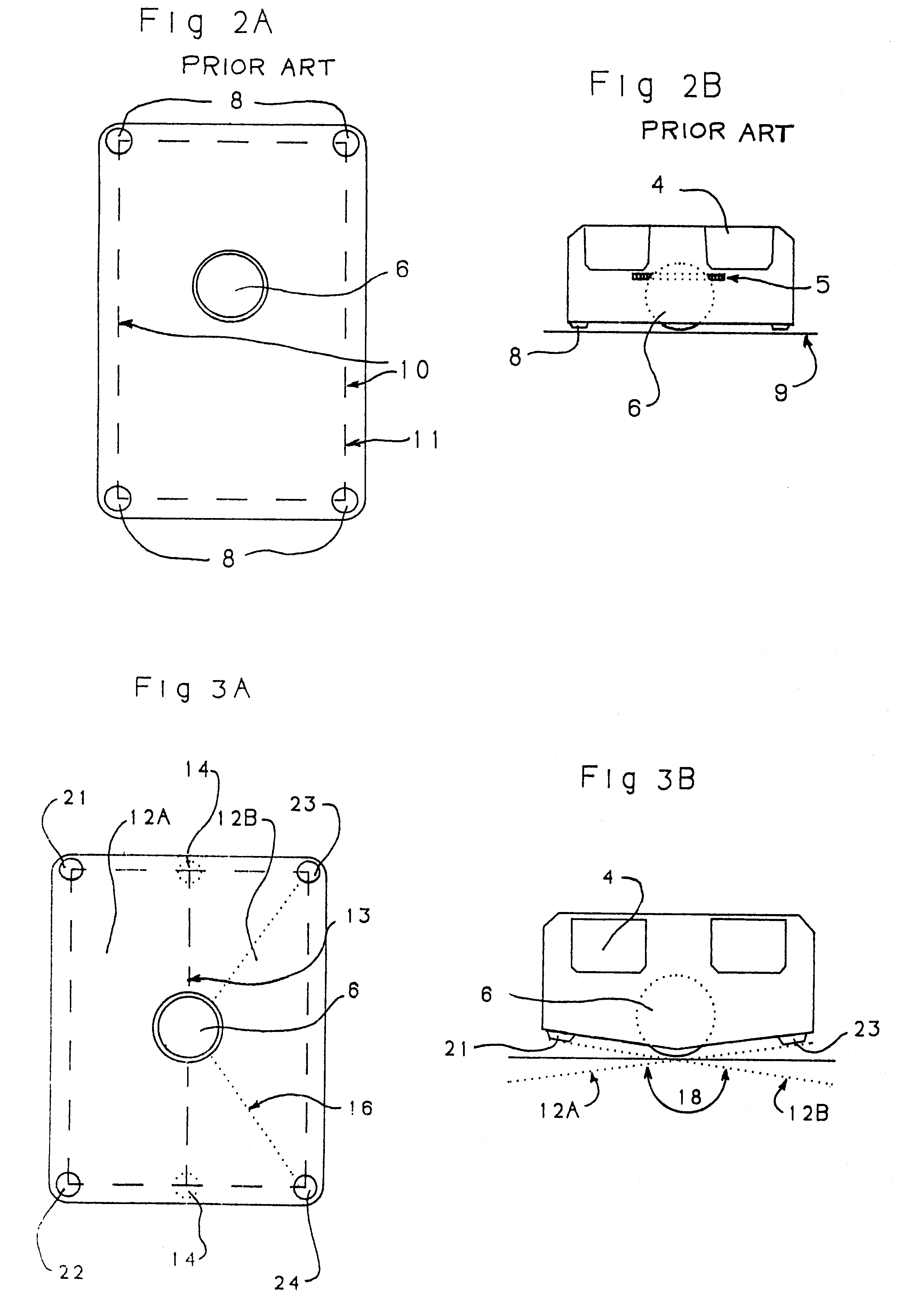
FIG. 1 is a perspective view of a conventional mouse 2, with keys 4 and a single plane bottom defined by feet 8. The tracking sphere 6 rides within the housing and is exposed generally in the center of the single plane 10 which the housing provides. Typically the sphere is loosely fitted in the housing with some play in the vertical dimension, so that the sphere may drop by its own weight so that the surface of its lower, exposed pole touches and rides (tangentially) the same desk surface which is congruent with the plane defined by the four feet. It is common for the upper pole of the sphere to have a circular bearing surface of smooth material that limits upward movement of the sphere, otherwise the sphere could be pushed out of sight and lost in the housing of the mouse. Similarly, a lower retainer plate 3 with a circular opening keeps the sphere from falling out of the housing.

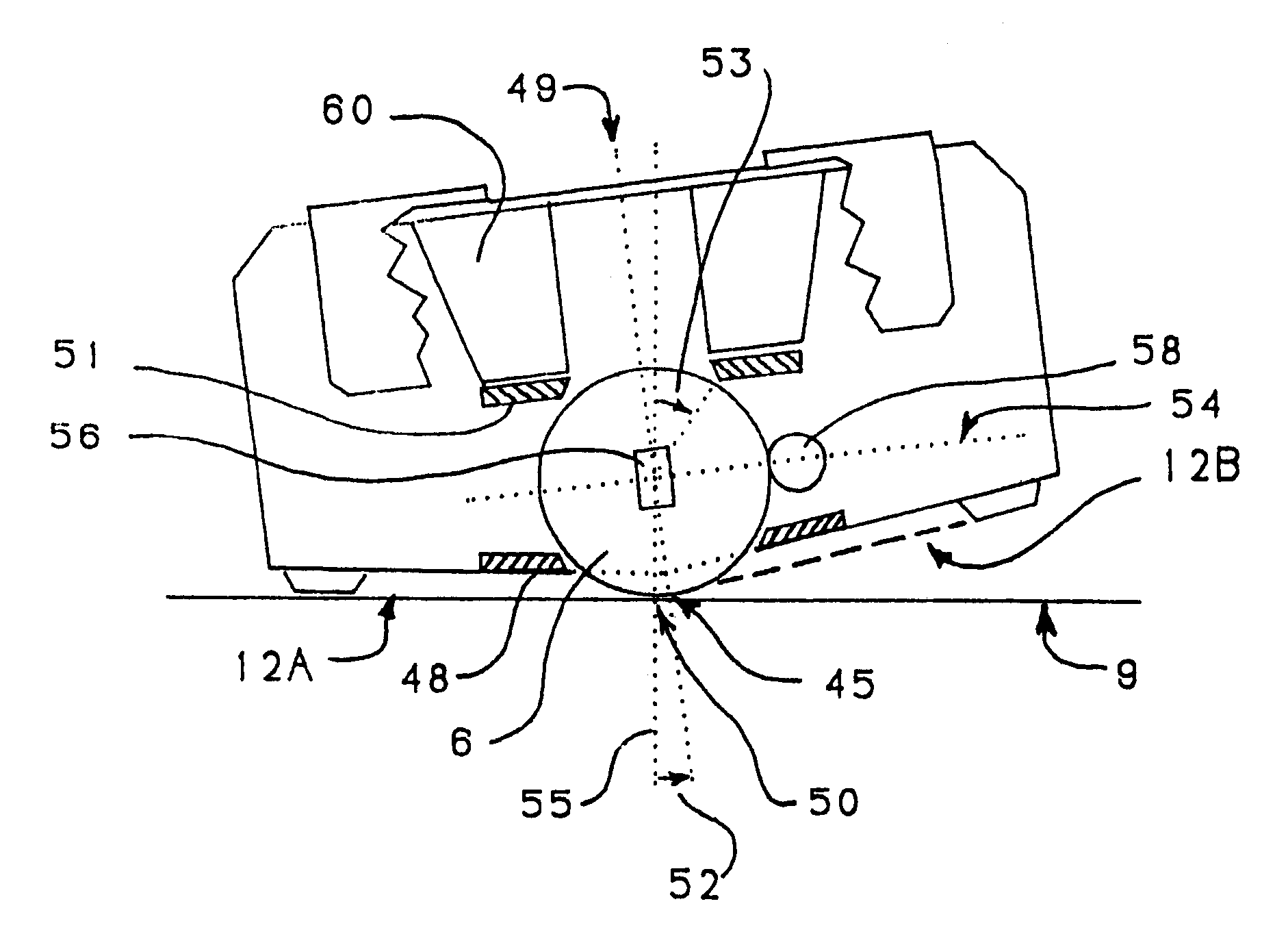
As discussed in the preceeding section ("Background of the invention") the tracking sphere commonly is ...


PUM


Abstract

A conventional monoplane mouse is constructed to move on a flat surface upon a single plane within which a contained sphere may rotate tangential with the single plane contacting the flat surface. Signal for XY cursor movement are derived from two or more counting sensors positioned at an equator of the rotatable sphere parallel with the single plane. The mouse invention defines two or more facets in the underside housing. The facet mouse can be tilted to one of the exclusive facets and moved on a flat surface to generate XY signals. The facet plane selected by tilt is identified by triggered pressure sensitive switches at each facet plane. The switches also function as undercarriage feet to define the virtual plane of contact to the flat surface. The facet planes in two and four facet embodiments are oriented with the orthogonally placed sphere counting sensors so that the interest of any two opposing facets is parallel with the plane of rotation of one of the counting wheels. A single sphere and counter apparatus can serve all facets, being placed at the intersect of all facets. To aid the hand in applying continuous downward pressure to the mouse onto a preferred facet, a hinged and elevatable palm hood is attached to the top of the mouse. The mouse enables a new user interface beyond the tradition ones of: 1.clicking keys by a finger and 2.whole arm movement of a mouse on an XY surface. By a tilting wrist motion, the user may instantly and continuously toggle 2,4, or more selection assigned to the facets provided.

Description

BACKGROUND IN THE FIELD OF THE INVENTIONThe mouse has become a common device for control of cursor movement on a CRT screen. All mice employ the principle of a contained sphere rolling on a surface, generally a flat desktop. Two counting wheels are positioned around the sphere, usually at the horizontal equator; the wheels are positioned with axes of rotation that are orthogonally at 90 degrees to each other. A third wheel is usually provided as a tensioning roller placed near the same equator on the opposite side of the sphere for the purpose of keeping the sphere in contact with the two counting wheels. The housing of a typical mouse also provides means for keeping the polar or vertical axis of the sphere stabilized during rolling motions. The housing usually exposes only the extreme bottom pole of the sphere which of course rolls on a desk or pad surface; the sphere usually protrudes from the flat underside of the mouse housing. Since the housing may carry a panel for removal and...

Claims


Application Information

Patent Timeline
Patent Type & Authority Patents(United States)
IPC IPC(8): G06F3/033G06F3/039
CPCG06F3/03543G06F3/039Y10T74/20201G06F2203/0333
Inventor MAYNARD, JR., STUART TYRUS
Owner MAYNARD JR STUART TYRUS
Why Eureka
Try Eureka