Method and system for high speed detailed placement of cells within an integrated circuit design

a technology of integrated circuit design and cell placement, applied in the field of electronic design automation, can solve the problems of complex modern electronic circuit design, the cell placement determined by the coarse placer process may not be legal, and the complexity of modern integrated circuit design is much too large for circuit designers or even engineers of designers to manage effectively by manual techniques

Inactive Publication Date: 2002-04-09
SYNOPSYS INC
View PDF2 Cites 58 Cited by
  • Summary
  • Abstract
  • Description
  • Claims
  • Application Information

AI Technical Summary

Problems solved by technology

The rapid growth of the complexity of modern electronic circuits has forced electronic circuit designers to rely upon computer programs to assist and automate most steps of the integrated circuit design process.
Modern integrated circuit designs are much too large for a circuit designer or even an engineering team of designers to manage effectively by manual techniques.
However, the cell locations assigned by the coarse placer process are not initially legal locations for the cells because the coarse placer process assigns precise cell coordinates using floating point values.
Also, the cell locations determined by the coarse placer process may not be legal due to cell-to-cell overlaps or overlaps between cells and small obstacles.
The detailed placement process generally does not attempt to improve wire length of the design, rather, it slightly degrades wire length in an effort to arrive at legal cell placements.
Therefore, these initial cell placements are not legal.
This detailed placement process of the prior art has a disadvantage in that many cells, after being snapped to their nearest grid locations, end up overlapping other cells, sometimes causing thousands of overlaps.
The problem is severe because when the detailed placer process attempts to move an overlapping cell to another location, it must also check for a possible overlap condition at the new location, and so forth.
This process of moving cells, checking for overlapping conditions and moving cells, etc., can take many iterations per cell thereby consuming a relatively large amount of processing time.
In an effort to reduce this problem, complex, detailed and time consuming programming processes are introduced which add processing penalties and technical complexities to the detailed placer process.
In addition to taking a relatively large amount of processing time to complete, this prior art method of detailed placement also causes some cells to be moved quite a distance from their original position in order to locate a non-overlapping site.
Another disadvantage of this prior art detailed process is that it does not fully take advantage of the two dimensional nature of the detailed placement problem and thereby generates cell placements that are not typically uniform in nature.
Another disadvantage of this detailed cell placement process is that it does not easily or readily deal with cell obstructions.
Some candidate sites are invalid due to the presence of obstructions or incompatible metal layers in the integrated circuit design.
However, because this bias effects the entire design the same way it tends to cancel itself out.

Method used


Image

  • Method and system for high speed detailed placement of cells within an integrated circuit design
  • Method and system for high speed detailed placement of cells within an integrated circuit design
  • Method and system for high speed detailed placement of cells within an integrated circuit design

Examples


Embodiment Construction

FOR OBSTRUCTIONS AND INVALID CELL AREAS

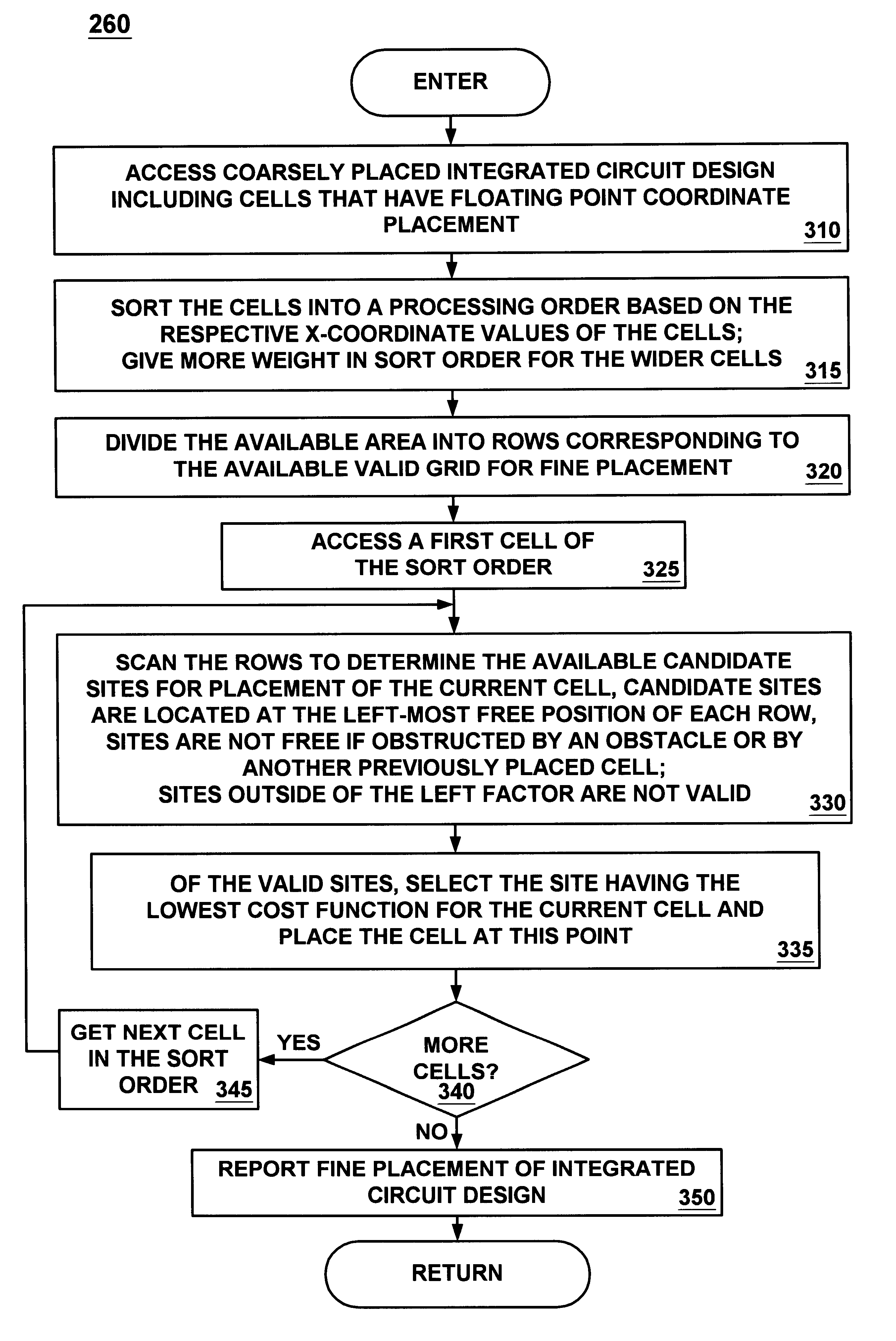
FIG. 7A and FIG. 7B illustrate another example of the processing of step 330 and step 335 of the detailed placer 260 of the present invention. This example illustrates that the process of the detailed placer 260 of the present invention can inherently deal with obstructions in the same manner as it deals with placed cells. FIG. 7A illustrates an exemplary layout portion 610 having cells 620a-620i that have already been detailed placed by process 260. Cells 630a-630b remain to be detailed placed and, specifically, cell 630a is the current cell to be placed by process 260. According to this scenario, the candidate sites for placement of cell 630a, as determined by step 465, are shown as 625a-625g. The cell based boundary line for cell 630a is shown as boundary line 615. Candidate site 625d is determined based on the presence of the obstruction 622 which is treated like a previously placed cell to process 330. Memory cell locations can create obst...


PUM


Abstract

A method and system for high speed detailed placement of cells within an integrated circuit design. The novel detailed placement system receives a set of cells of an integrated circuit design where the cells have undergone coarse placement. Cells have variable width but the same height (or vice-versa). The cells are each assigned an initial coordinate position, e.g., using floating point precision values. During detailed placement, the cell coordinates are assigned to x-axis and y-axis grid lines. The detailed placement process sorts the cells based on their coordinates along a first axis, e.g., their x-axis coordinates; sort order dictates cell placement order. In one embodiment, sort order preference is given to the wider cells. For a given cell, placement is performed by scanning through the rows of the substrate and selecting the left-most positioned vacant site of each row as a candidate site for placement. A site is vacant if it does not contain a previously placed cell. Of the candidate sites, a valid site having the lowest cost (e.g., the nearest site) is selected for the cell. Some candidate sites are invalid due to the presence of obstructions or incompatible metal layers. A candidate site can also be invalid if it lies too far to the left of the cell, based on a left factor. Placement from left to right along the rows continues in this manner until all cells are placed. Alternatively, the process could run right to left, down to up or up to down.

Description

1. Field of the InventionThe present invention relates to the field of electronic design automation (EDA). More specifically, the present invention relates to layout placement of cells within the field of electronic design automation used in the design and fabrication of integrated circuit devices.2. Related ArtThe rapid growth of the complexity of modern electronic circuits has forced electronic circuit designers to rely upon computer programs to assist and automate most steps of the integrated circuit design process. Typical circuits today contain hundreds of thousands or millions of individual pieces or "cells." In many design architectures, the cells can have variable widths but constant heights or the cells can have variable heights but constant widths. Modern integrated circuit designs are much too large for a circuit designer or even an engineering team of designers to manage effectively by manual techniques. To automate the circuit design and fabrication of integrated circui...

Claims


Application Information

Patent Timeline
Patent Type & Authority Patents(United States)
IPC IPC(8): G06F17/50
CPCG06F17/5072G06F30/392
Inventor HILL, DWIGHT
Owner SYNOPSYS INC
Why Eureka
Try Eureka