Placement ring assembly having magnetic securing means

a technology of magnetic securing means and placement rings, which is applied in the direction of manufacturing tools, ceramic shaping cores, coatings, etc., can solve the problem of difficult disassembly of placement rings after the cast member

Inactive Publication Date: 2002-04-16
WESTHOFF JAMES A +1
View PDF6 Cites 15 Cited by
  • Summary
  • Abstract
  • Description
  • Claims
  • Application Information

AI Technical Summary

Benefits of technology

It is therefore one object of the present invention provided a novel mandrel assembly for placement of a pipe connector gasket for accurate placement of a pipe connector gasket within a mold assembly utilizing magnetic means which accurately positions the pipe connector gasket and the inner and outer mandrels along the mold assembly without the need for additional fastening or positioning members.
Still another object of the present invention is to provide a mandrel assembly of the type described and in which the magnetic holding means is provided with a mechanical release, eliminating the need for additional tools for removing the permanent magnet and hence the mandrel assembly from the mold assembly.
Still another object of the present invention is to provide a mandrel assembly for positioning a pipe connector gasket within a mold assembly and which is provided with shock absorbing knockout pads to facilitate separation of the mandrels after a casting operation while preventing the mandrel members from being damaged.
Still another object of the present invention is to provide a one-piece type hole former provided with magnetic means to secure the hole former in proper position when casting a member in a mold and having a mechanical release for easily separating the hole former when the cast member has set.

Problems solved by technology

In addition, cast material as well as any other contaminants make it difficult to disassemble the placement rings after the cast member has been set.

Method used


Image

  • Placement ring assembly having magnetic securing means
  • Placement ring assembly having magnetic securing means
  • Placement ring assembly having magnetic securing means

Examples


Embodiment Construction

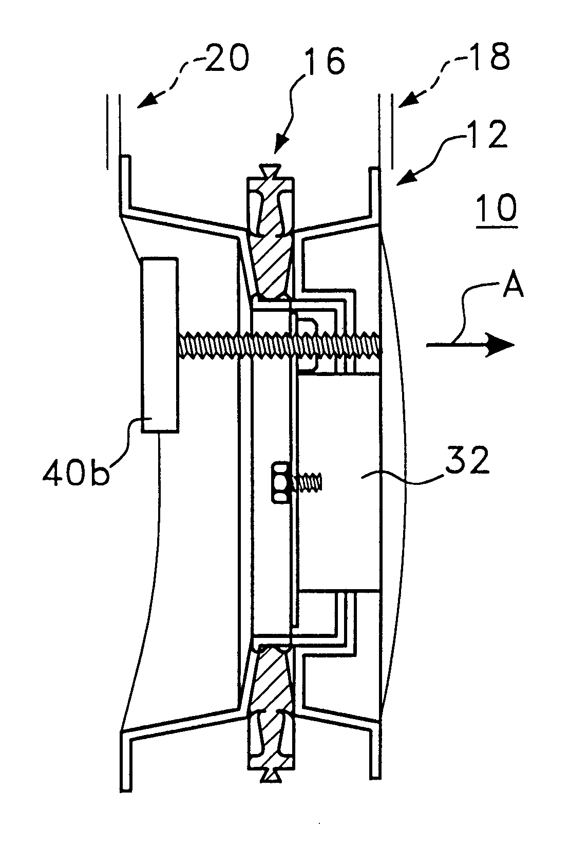
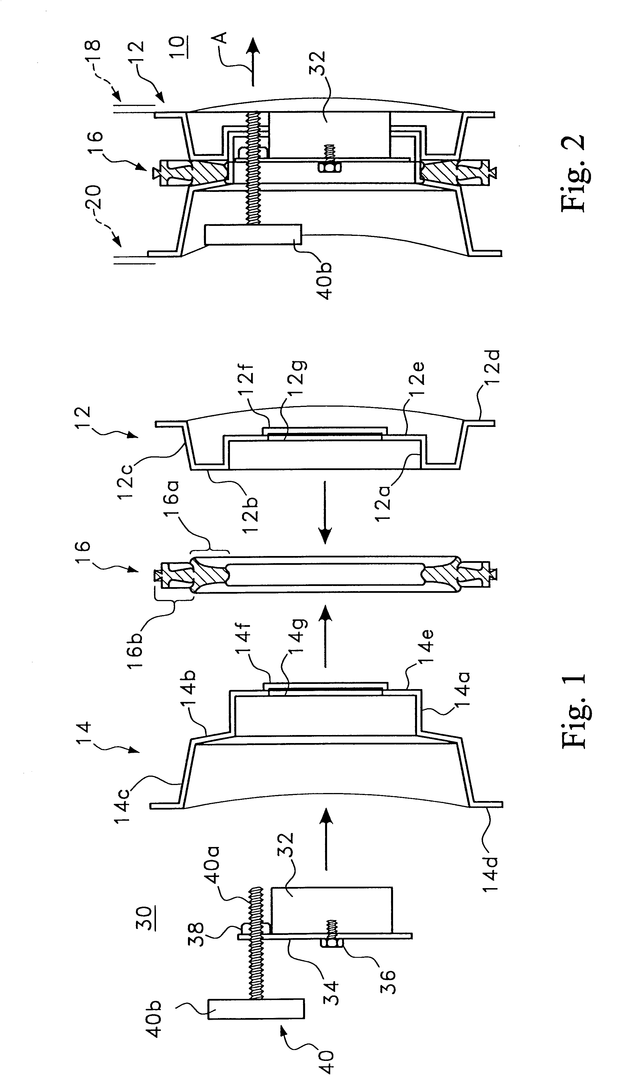
Making reference to FIGS. 1 and 2, the mandrel assembly 10 of the present invention is comprised of inside and outside mandrels 12 and 14 arranged to be assembled in the manner shown in FIG. 2 so as to accurately position a pipe connector gasket 16 therebetween. The cylindrical-shaped surface portion 14a, which is slightly tapered, is embraced by the cylindrical-shaped slightly tapered portion 12a. The flat surface portion 12b of inside mandrel 12 and the significantly tapered portion 14b of outside mandrel 14 embrace the inside portion 16a of gasket 16. The outer portion 16b of gasket 16 extends beyond portions 12b and 14b as can best be seen in FIG. 2 and is arranged to be imbedded within the cast material. Tapered portions 14c and 12c of outside and inside mandrels 14 and 12, together with outwardly directive flanges 14d and 12d serve to define the opening in the member being cast, as well as the shape of the opening.

The right-hand surface of flange 12d rests against the surface ...


PUM

PropertyMeasurementUnit
diameteraaaaaaaaaa
diametersaaaaaaaaaa
metallicaaaaaaaaaa

Abstract

A placement ring assembly has inside and outside mandrels releasably fastened together to secure and align a pipe connector gasket therebetween. A permanent magnet of a magnet assembly is inserted through co-aligned openings in the mandrels and is magnetically attracted to an inner-core of a casting assembly. When the cast member is set, a mechanical release is rotated to release the magnetic attraction between the permanent magnet and the mold core. One of the mandrels may be provided with shock absorbing knockout pads while the other mandrel has openings aligned with the knockout pads to enable the knockout pads to be struck with a hammer to separate the mandrels. Rubber cushioning members absorb the shock of the impacts, protecting the mandrel from permanent damage. One-piece hole formers may likewise be provided with a magnetic assembly having a mechanic release as well as knock-out pads.

Description

The present invention relates to devices such as hole formers and placement rings for manhole pipe connectors cast into manhole assemblies and the like and more particularly to novel hole formers and novel two-part placement rings incorporating magnetic securement means and / or knockout means.RELATED ARTU.S. Pat. Nos. 3,796,406; 3,813,107; 3,832,438; 4,073,048; and 4,159,829.Hole formers and placement ring assemblies are well known in the manhole casting field and are typically respectively utilized to accurately define an opening within a manhole base or the like and further to accurately position a manhole pipe connector gasket or hole former having a portion thereof to be embedded within the cast material.Placement ring assemblies are conventionally formed of a metallic material and comprise first and second placement rings. A pipe connector gasket is positioned between cooperating circumferential portions of the rings and is maintained firmly clamped between the cooperating place...

Claims


Application Information

Patent Timeline
Patent Type & Authority Patents(United States)
IPC IPC(8): B28B23/00
CPCB28B23/0043B28B7/002
Inventor WESTHOFF, JAMES A.KELLY, JAMES A.
Owner WESTHOFF JAMES A
Why Eureka
Try Eureka