Coil assembly of rotating electrical machinery and method for producing the same, and stator of rotating electric machinery using the same coil assembly

a technology of rotating electrical machinery and coil assembly, which is applied in the direction of windings, dynamo-electric components, and magnetic circuit shapes/forms/constructions, etc., can solve the problems of low productivity, inefficient work, and difficulty in producing a small alternator

Inactive Publication Date: 2002-04-23
MITSUBISHI ELECTRIC CORP
View PDF7 Cites 91 Cited by
  • Summary
  • Abstract
  • Description
  • Claims
  • Application Information

AI Technical Summary

Problems solved by technology

Therefore, the work was inefficient and the productivity was low because it was necessary to insert numerous short conductor segments 1 into the slots of the stator iron core 2 and then join the ends one by one.
Moreover, since the end portions have to be protruded further to allow the ends to be clamped by a fixture for the joining process, it was difficult to produce a smaller alternator.

Method used


Image

  • Coil assembly of rotating electrical machinery and method for producing the same, and stator of rotating electric machinery using the same coil assembly
  • Coil assembly of rotating electrical machinery and method for producing the same, and stator of rotating electric machinery using the same coil assembly
  • Coil assembly of rotating electrical machinery and method for producing the same, and stator of rotating electric machinery using the same coil assembly

Examples


embodiment 1

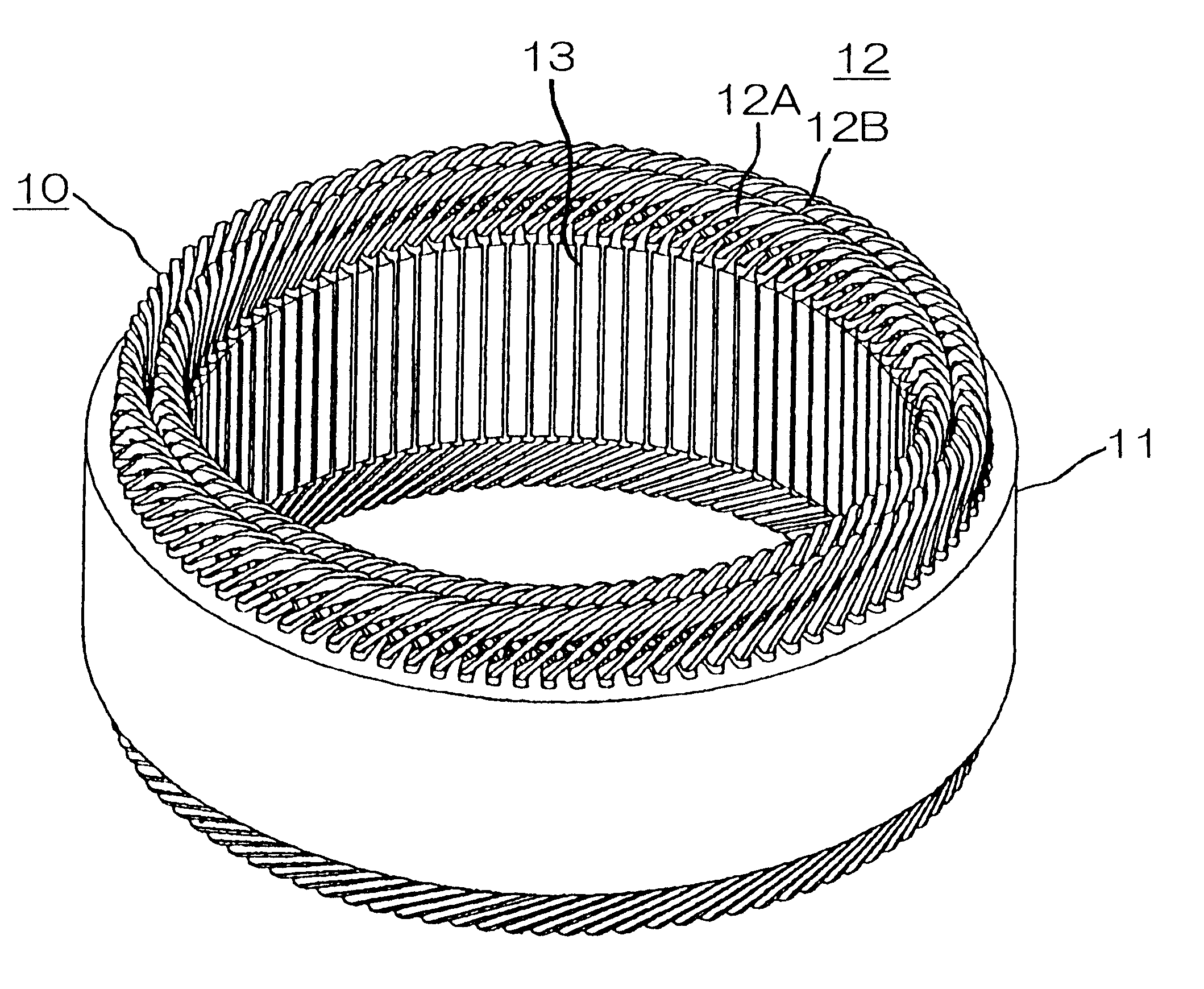
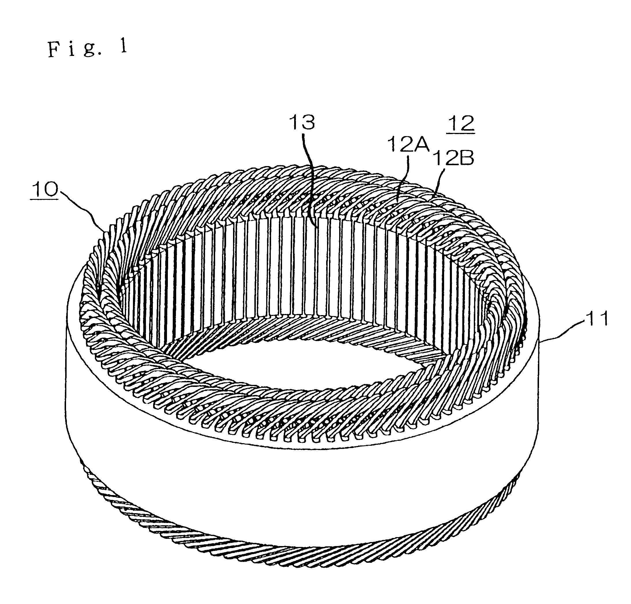
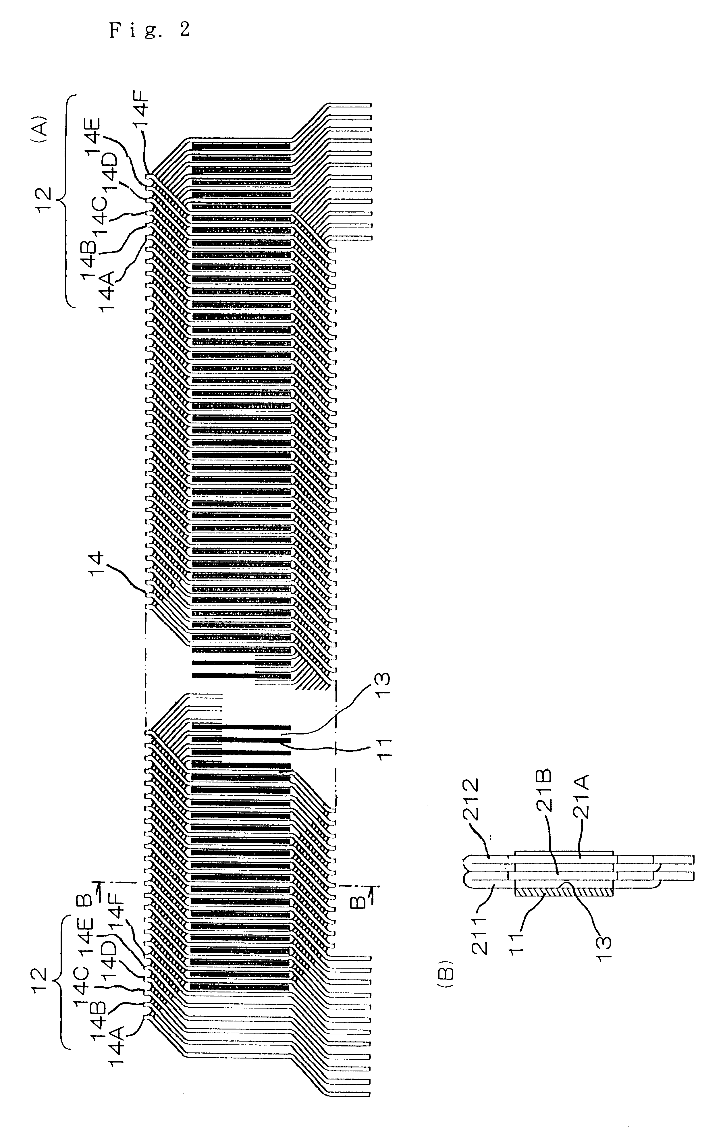
FIG. 1 is a perspective view showing the appearance of a stator of an alternate current generator for a vehicle, to which a coil assembly according to a first embodiment of the invention is applied. FIG. 2 shows the construction of the coil assembly in FIG. 1, which is developed together with the stator, wherein (A) is a developed front elevational view, and (B) is a side elevational view observed along the line B--B in (A). FIG. 3 is a developed front elevational view showing the developed construction of the coil assembly in FIG. 1. FIG. 4 is a perspective view showing a part of the construction of one coil assembly in FIG. 3. FIG. 5 is a perspective view showing a part of the construction of one coil combination in FIG. 3.

FIG. 6 shows the production process of the coil member in FIG. 3, wherein (A) shows a winding step, and (B) shows a displacing step. FIG. 7 shows the construction of a flat-type stator iron core, wherein (A) is a plan view, and (B) is a side elevational view. FI...

embodiment 2

FIG. 16 is a view showing a step in a method for producing a coil assembly of rotating electrical machinery according to the second embodiment. FIG. 17 is a view showing a step, which is different from the step in FIG. 16, in a method for producing a coil assembly of rotating electrical machinery according to the second embodiment. FIG. 18 is a block diagram showing steps in a method for producing a coil assembly of rotating electrical machinery according to the second embodiment. FIG. 19 is a perspective view showing the appearance a stator of an alternate current generator for vehicles, which is different from FIG. 1 in which coil members in the first and second embodiments are applied. FIG. 20 is a view showing a method that is different from the method in FIG. 16 showing the steps of producing a coil assembly in the second embodiment of the invention.

A coil assembly of rotating electrical machinery secured by the second embodiment is similar to that in which a coil assembly 12 a...

embodiment 3

FIG. 21 is a perspective view showing the appearance of a stator of an alternate current generator for vehicles, to which a coil according to the third embodiment of the invention is applied, FIG. 22 is a perspective view explaining the profile of the first coil in FIG. 21, FIG. 23 is a perspective view explaining an array profile of the first coil member in FIG. 21, FIG. 24 is a perspective view explaining the profile of the second coil member in FIG. 21, FIG. 25 is a perspective view explaining an array profile of the second coil member in FIG. 21, and FIG. 26 is a perspective view explaining an array of combinations of coil combinations in FIG. 21.

In the drawings, parts which are identical to those of the first embodiment are given the same reference numbers, and overlapping description thereof is omitted. The first coil members 35 is formed of one strip conductor having a width W and a thickness T as in the coil member 21 in the first embodiment described above. And, the first c...


PUM


Abstract

The invention provides a coil member of rotating electrical machinery, by which improvements in the mass production and downsizing thereof are enabled, which is a coil assembly for rotating electrical machinery, consisting of a plurality of coil combinations mounted at iron core slots, wherein the respective coil combinations 14 are inserted into slots at pitches equivalent to an appointed number of slots, and are formed of an integral coil member 21 in which the first and the second linear portions 21A and 21B alternately disposed at the inner layer side and the outer layer side in the slots, and the first and the second turning portions 21C and 21D for connecting the first and second linear portions 21A and 21B adjacent to each other outward of one end side and outward of the other end side in the lengthwise direction of the slots are integrated together. And, the first linear portion 21A of the appointed coil member 211 thereof, and the second linear portion 21B of another coil member 211 are laminated and disposed in the same slots.

Description

1. Field of the InventionThe present invention relates to a coil assembly of rotating electrical machinery such as a vehicle alternate current generator, etc., that is incorporated in a truck, etc., and a method for producing the same coil assembly, and a stator of rotating electric machinery using the same coil assembly,2. Description of the Prior ArtIn order to make the vehicle alternate current generator more compact and more powerful for its size, it is mandatory to improve the space factor inside each slot of the core of the stator winding, and to arrange more neatly and increase the density of the cross-over parts on the outside of the slots of the stator winding, i.e., the coil end parts. Numerous improvements have been proposed as exemplified by Japanese Patent No. 2927288 concerning this point.FIGS. 27 (A) and (B) are perspective views of the essential parts of the stator winding of an automobile alternator of the prior art viewed from the front and rear sides respectively,...

Claims


Application Information

Patent Timeline
Patent Type & Authority Patents(United States)
IPC IPC(8): H02K3/14H02K3/12H02K1/16H02K1/18H02K3/04H02K3/28H02K15/04H02K15/085H02K19/16
CPCH02K3/14H02K15/0478H02K15/085
Inventor MURAKAMI, TSUTOMUOZAKI, HIRONORIOKETANI, NAOHIROMORISHITA, AKIRAMATSUI, HIROSHITAKAHASHI, TSUYOSHIADACHI, KATSUMITAKIZAWA, TAKUSHIASAO, YOSHIHITOOOHASHI, ATSUSHI
Owner MITSUBISHI ELECTRIC CORP
Why Eureka
Try Eureka