
Method and system for staging data into cache

a technology for staging data and cache, applied in the direction of memory adressing/allocation/relocation, instruments, computing, etc., can solve the problems of inability to adjust the rate of staging and/or the number of tracks staged, too many or too few tracks will be staged into cache, and the reading unit moving to the disk section to read data is often a time-consuming process

Inactive Publication Date: 2002-04-30
IBM CORP
View PDF43 Cites 92 Cited by
  • Summary
  • Abstract
  • Description
  • Claims
  • Application Information

AI Technical Summary

Benefits of technology

Preferred embodiments seek to balance two competing goals. The first goal concerns providing sufficient tracks in cache to continuously make data available to DARs from host systems and avoid a cache miss. A cache miss occurs when the cache does not include the data requested by the host. The second goal concerns conserving available memory space in cache. To accomplish this second goal, too much data cannot be staged into cache in advance of when the DAR will be received. Otherwise, the staged data will remain unaccessed in cache and consume cache space which could otherwise be made available for other operations.
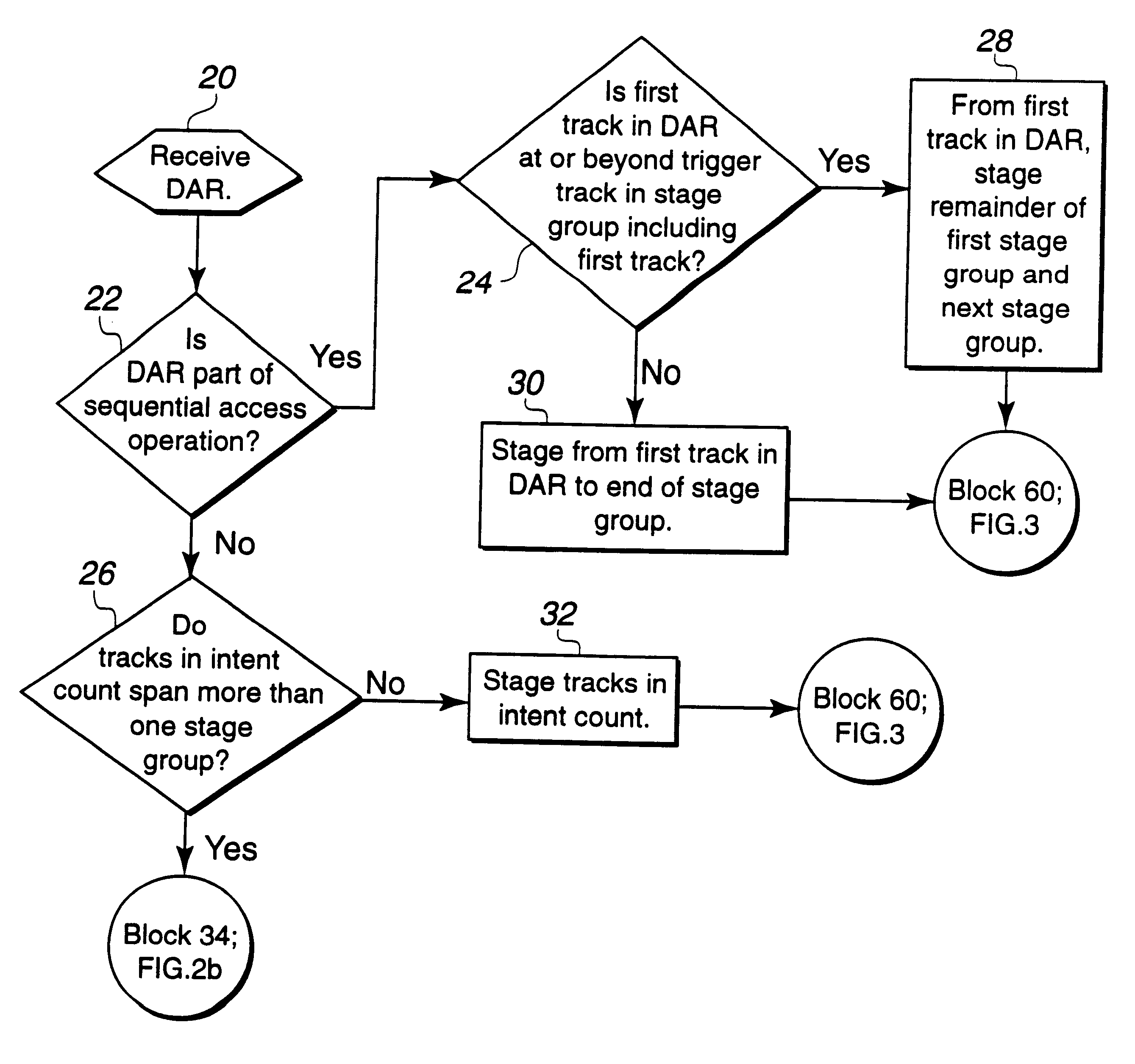
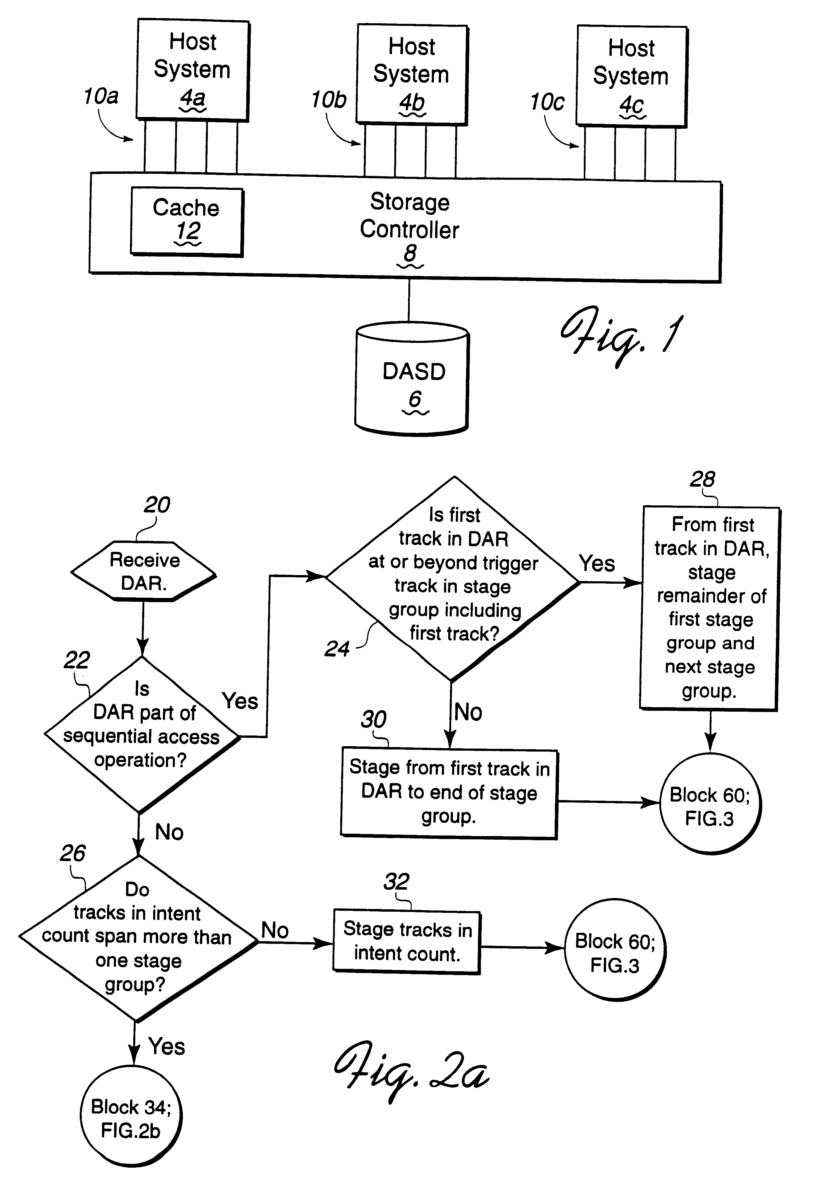
The storage controller 8 transfers data from the cache 12 across the channels 10a, b, c to the host systems 4a, b, c. In a sequential data access request, after transferring the data across the channel 10a, b, c, the storage controller 8 would stage the next stage group in anticipation of the data to access. In this way, the storage controller 8 does not have to access data directly from the DASD 6 and instead may access the data for a DAR from the cache 12. In the SCSI environment, if the storage controller receives a READ command having a transfer length of 64 blocks, wherein each block is 512 bytes, the storage controller 8 can stage eight blocks at a time into the cache 12. While the storage controller 8 is transferring an eight block group across the channels 10a, b, c to the host system 4a, b, c, the storage controller 8 would stage the next eight blocks into cache 12.
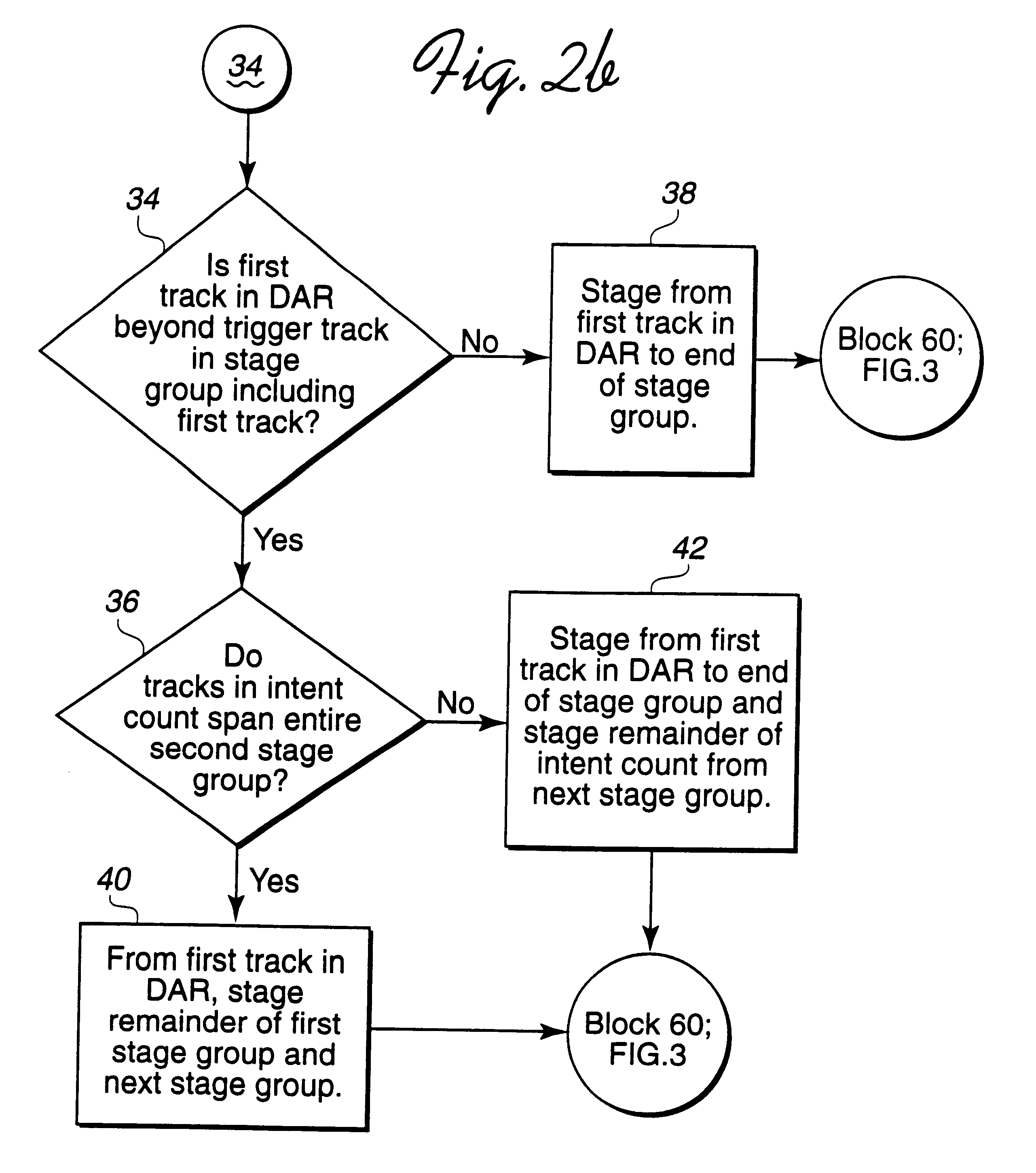
The storage controller 8 also maintains a "trigger track," which is an offset track within a stage group that when processed directs the storage controller 8 to stage the next stage group into cache 12. When the storage controller 8 reads the trigger rack when processing a DAR, the storage controller 8 then stages the next stage group into cache 12. In this way, the storage controller 8 limits the amount of data staged in cache 12 by controlling the number of stage groups staged at a time and controlling when to stage by designating a trigger track. The trigger track must be selected to balance two competing goals: (1) stage sufficiently ahead, i.e., earlier in the stage group, so that there is sufficient data to accommodate subsequent DARs versus (2) delay staging to minimize cache 12 usage. To balance these goals, the storage controller 8 may maintain different trigger tracks for different types of hosts and for sequential versus non-sequential data access requests. To provide a slower stage process to accommodate slower transfers of data from the cache 12 to the channels 10a, b, c, the trigger track would be located closer to the end of the stage group versus a trigger track located closer to the beginning of the stage group when the transfer speed is high.
There are two factors that effect how quickly data is accessed from cache. The first factor concerns the speed of the channel 10a, b, c and the second factor concerns the type of access operation, e.g., sequential or non-sequential. With respect to the first factor, with hosts 4a, b, c having slower channels 10a, b, c, data transfer from the cache 12 to the host is longer and data remains staged in cache for a longer period of time. To accommodate slower hosts, the storage controller 8 can locate the trigger track closer to the end of the stage group, e.g., ten tracks from the end of the stage group, to delay staging of the next stage group. On the other hand, to accommodate hosts 4a, b, c having faster channel 10a, b, c data transfer rates, the storage controller 8 would locate the trigger track closer to the beginning of the stage group, e.g., an offset of 15 tracks, to stage the data into cache 12 earlier because the DARs are more frequent, thus requiring more data readily available in the cache 12.
With respect to the second factor, sequential data accesses are often accessed less frequently than non-sequentially accessed data. Sequential requests are often made when the host 4a, b, c is requesting blocks of data to set-up for an operation. In such case, the host 4a, b, c may not access the data immediately. On the other hand, non-sequential accesses are often for application access requests that need the entire block of requested data immediately in order to proceed. Thus, for sequential data accesses, the storage controller 8 can locate the trigger track closer to the end of the stage group to slow the stage rate. The stage rate may be slowed to accommodate the less frequent data accesses that occur during sequential accesses. Alternatively, for non-sequential accesses, the storage controller 8 can locate the trigger track closer to the beginning of the stage group to stage data sooner because with non-sequential accesses, the data accesses are more frequent.
In preferred embodiments, the storage controller 8 may adjust the stage group size to optimize the two competing goals: staging enough tracks so requested tracks are always available in cache and minimizing the number of tracks staged to conserve cache 12 resources. By reducing the stage group size, the storage controller reduces the number of tracks staged and increases the likelihood that the tracks needed for a subsequent DAR will not be available in cache 12. By increasing the stage group size, the storage controller 8 increases the likelihood that the tracks needed for any DAR will be available in cache 12. FIGS. 5, 6, and 7 illustrate logic implemented by the storage controller 8 to adjust the stage group size. The logic of FIGS. 5 and 6 maintains parameters that are used to trigger changes in the stage group size (SGS). These parameters include the busy_for_stg counter which indicates the number of times the storage controller 8 attempted to process a DAR and the requested tracks were being staged to the cache 12. The parameter prestg_no_acc indicates the number of times the storage controller 8 demoted a track from cache 12 that was staged and had not yet been accessed by a host system 4a, b, c.

Problems solved by technology

The process of physically rotating the disk in the DASD to the requested track then physically moving the reading unit to the disk section to read data is often a time consuming process.
One problem with current staging systems is the inability to adjust the rate of staging and / or the number of tracks staged to accommodate variances in DARs.
If the number of tracks staged is not carefully controlled, then too many or too few tracks will be staged into cache.
Staging too few tracks will delay responding to DARs because the response to the DAR will have to wait while the requested data is staged in from DASD.
On the other hand, staging too much data into cache in advance of when the data is needed will result in wasted cache space.
In such case, the demoted staged data will not be available for the anticipated DAR.

Method used


Image

  • Method and system for staging data into cache
  • Method and system for staging data into cache
  • Method and system for staging data into cache

Examples


embodiments and conclusion

Alternative Embodiments and Conclusion

The preferred embodiments may be implemented as a method, apparatus or article of manufacture using standard programming and / or engineering techniques to produce software, firmware, hardware, or any combination thereof. The term "article of manufacture" (or alternatively, "computer program product") as used herein is intended to encompass one or more computer programs and data files accessible from one or more computer-readable devices, carriers, or media, such as a magnetic storage media, "floppy disk," CD-ROM, a file server providing access to the programs via a network transmission line, holographic unit, etc. Of course, those skilled in the art will recognize that many modifications may be made to this configuration without departing from the scope of the present invention.

Preferred embodiments were described with respect to the IBM mainframe environment, where data is requested in tracks. However, those skilled in the art will appreciate th...


PUM


Abstract

Disclosed is a system for caching data. After determining a sequential access of a first memory area, such as a direct access storage device (DASD), a processing unit stages a group of data sets from the first memory area to a second memory, such as cache. The processing unit processes a data access request (DAR) for data sets in the first memory area that are included in the sequential access and reads the requested data sets from the second memory area. The processing unit determines trigger data set from a plurality of trigger data sets based on a trigger data set criteria. The processing unit then stages a next group of data sets from the first memory area to the second memory area in response to reading the determined trigger data set.

Description

1. Field of the InventionThe present invention relates to a method and system for staging data from a memory device to a cache and, in particular, staging data in anticipation of data access requests.2. Description of the Related ArtIn current storage systems, a storage controller manages data transfer operations between a direct access storage device (DASD), which may be a string of hard disk drives or other non-volatile storage devices and host systems and their application programs. To execute a read operation presented from a host system, i.e., a data access request (DAR), the storage controller must physically access the data stored in tracks in the DASD. A DAR is a set of contiguous data sets, such as tracks, records, fixed blocks, or any other grouping of data. The process of physically rotating the disk in the DASD to the requested track then physically moving the reading unit to the disk section to read data is often a time consuming process. For this reason, current system...

Claims


Application Information

Patent Timeline
Patent Type & Authority Patents(United States)
IPC IPC(8): G06F12/08
CPCG06F12/0862G06F2212/312G06F12/0866
Inventor BEARDSLEY, BRENT CAMERONBENHASE, MICHAEL THOMASHYDE, JOSEPH SMITHJARVIS, THOMAS CHARLESMARTIN, DOUGLAS A.MORTON, ROBERT LOUIS
Owner IBM CORP
Learn More