Traffic speed surveillance and control system

a control system and traffic speed technology, applied in traffic control systems, analog and hybrid computing, electric signalling details, etc., can solve the problems that the traffic surveillance systems described above have not received broad commercial success

Inactive Publication Date: 2002-05-07
AL AHMED KHALED A
View PDF4 Cites 49 Cited by
  • Summary
  • Abstract
  • Description
  • Claims
  • Application Information

AI Technical Summary

Problems solved by technology

The traffic surveillance systems described above have not received broad commercial success.

Method used


Image

  • Traffic speed surveillance and control system
  • Traffic speed surveillance and control system
  • Traffic speed surveillance and control system

Examples


Embodiment Construction

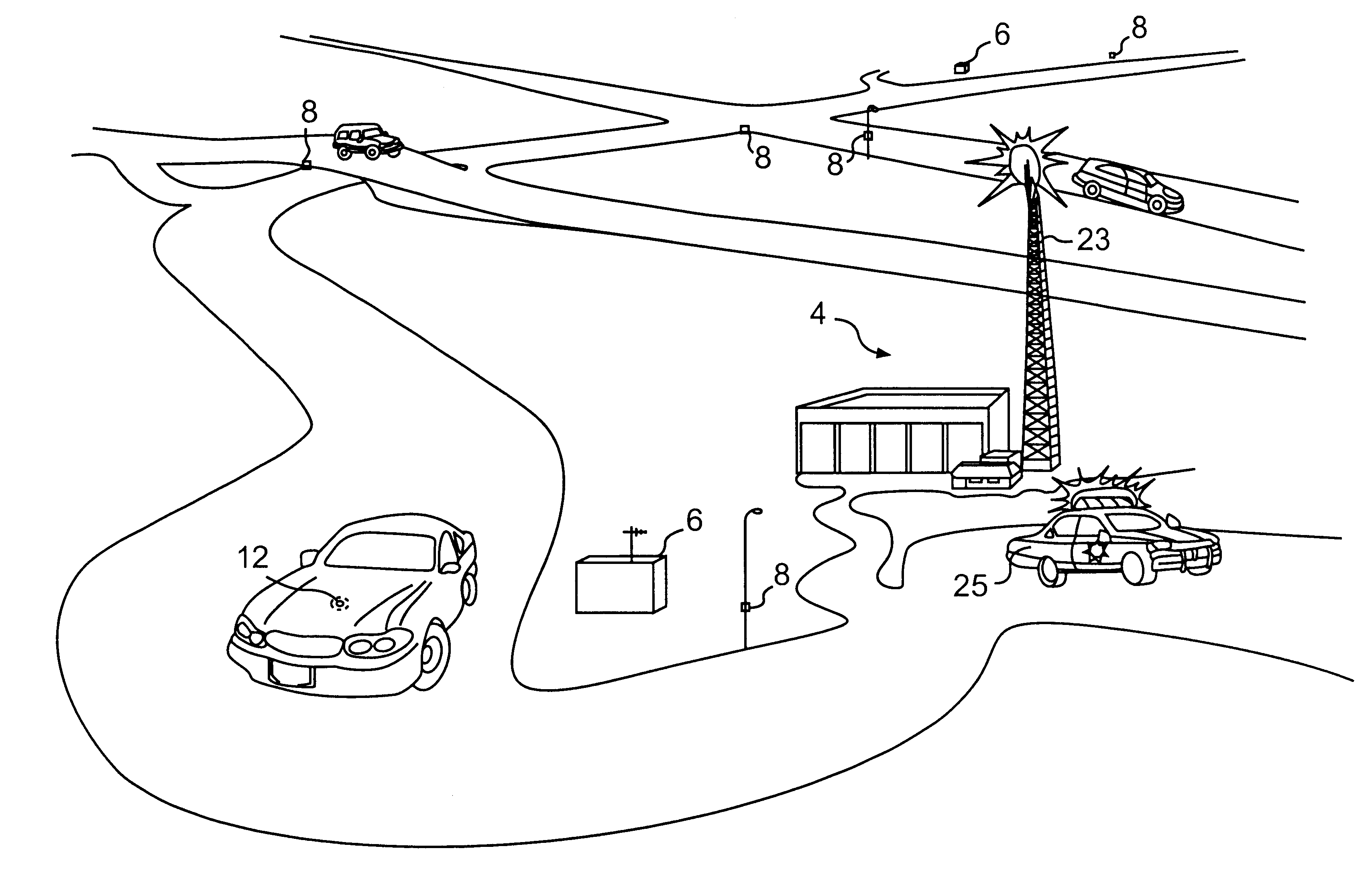
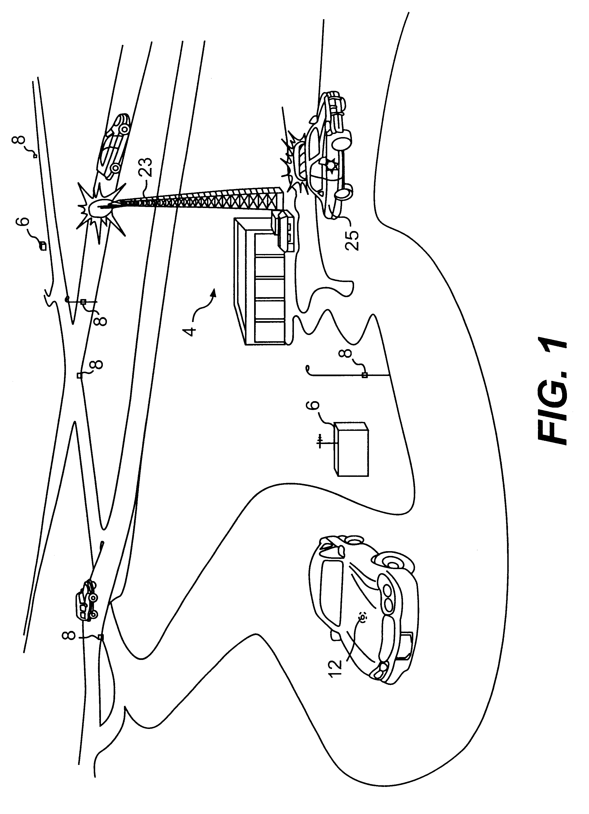
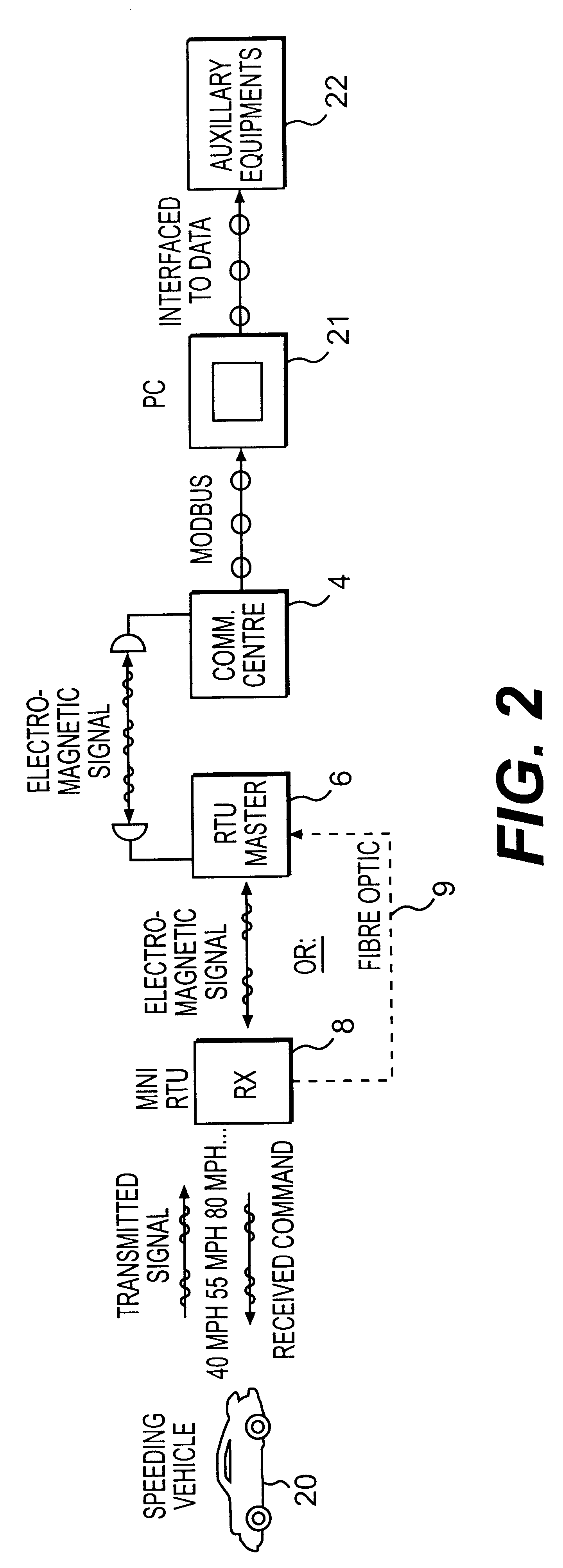
As shown in FIGS. 1 and 2, a traffic speed surveillance and control system according to the present invention includes a master communication center 4 and a plurality of master remote terminal units 6 for transmitting signals from the master remote terminal unit 6 to the master communication center 4. In a preferred embodiment of the invention, the master remote terminal units 6 includes means for the wireless transmission of signals to the center 4. For example, any conventional wireless transmission device may be incorporated in the system.

The traffic speed surveillance and control system also includes a plurality of detectors or mini remote terminal units 8. These mini remote terminal units 8 are disposed along a highway and adapted to receive signals from a passing vehicle. Such signals provide a vehicle identification number, driver's identification number and speed of the passing vehicle are transmitted. The mini remote terminals may be disposed on light posts, bridge abutment...


PUM


Abstract

A traffic speed control and surveillance system includes a speed sensor, vehicle identifier and transmitter/receiver disposed in a motor vehicle. The system also includes a plurality of mini remote terminal units disposed along a highway for monitoring signals from passing motor vehicles. Those signals identify the vehicle and speeds of those vehicles. The system also includes a communication center and one or more master remote terminal units for linking the mini remote terminal units to the communication center which processes the information. The communication center may also transmit a signal to disable the engine of an offending vehicle.

Description

This invention relates to a traffic speed and control system for motor vehicles and more particularly to an improved traffic speed and control system that records and reports speed limit violations and alerts patrol cars of vehicles being driven at an excessive rate of speed and their location.BACKGROUND FOR THE INVENTIONTraffic surveillance and control systems for motor vehicles are well known. For example, U.S. Pat. No. 3,680,043 of Angeloni discloses a system for monitoring the speed of highway vehicles from a central control station. The system includes posting devices positioned at intervals along the highway and adapted to receive a speed message from the control station and transmit the speed message to passing vehicles in a limited region of the highway in the form of an r-f signal. Each vehicle contains an r-f receiver which is connected to the vehicle speedometer or other vehicle identification means in a manner that will provide, upon the occurrence of some predetermined ...

Claims


Application Information

Patent Timeline
Patent Type & Authority Patents(United States)
IPC IPC(8): G08G1/017G08G1/052
CPCG08G1/052G08G1/017
Inventor AL-AHMED, KHALED A.
Owner AL AHMED KHALED A
Why Eureka
Try Eureka