Allocation of bandwidth in a packet switched network among subscribers of a service provider

a packet switching network and service provider technology, applied in data switching networks, frequency-division multiplexes, instruments, etc., can solve the problems of increasing reliance on the cooperation of host end systems, inability to guarantee a quality of service level, and inability to provide any form of traffic isolation among different users

Inactive Publication Date: 2002-05-07
SOUND VIEW INNOVATIONS
View PDF4 Cites 37 Cited by
  • Summary
  • Abstract
  • Description
  • Claims
  • Application Information

AI Technical Summary

Benefits of technology

The present invention provides a method for allocating bandwidth to a subscriber in a service provider domain that is part of a packet switched network such as the Internet, for example. In accordance with the method, a number of shares of bandwidth are assigned to the subscriber based on a contractual agreement between the subscriber and the service provider. A subscriber identifier and the number of shares assigned thereto are distributed to the routers in the domain of the service provider. The routers will in turn allocate bandwidth to packets they receive based on the number of shares assigned to the subscriber transmitting or receiving the packet. The subscriber may include one or more different user terminals that aggregate traffic onto a single datastream. The shares assigned to the user may denote an absolute amount of bandwidth, or alternatively, may denote a relative bandwidth allocation.

Problems solved by technology

The best-effort model does not provide any form of traffic isolation among different users, however, and thus resources are shared only on the basis of how much bandwidth a user requests.
Reliance on the cooperation of the host end systems is increasingly becoming unrealistic.
Inevitably, users attempt to exploit the weakness of the best-effort model to gain more resources.
Moreover, with the best-effort model it is impractical to guarantee a quality of service level, either in terms of an absolute or relative amount of bandwidth, because all traffic is integrated into a single datastream or flow.
However, end-to-end resource reservation methods encounter a number of problems when implemented over the Internet.
For example, it is difficult for an application to accurately characterize traffic on an a priori basis.
Additionally, end to end resource reservation methods do not work well for applications based on the World Wide Web, which are often characterized by sessions of very short duration.
However, for sessions of short duration there is a high overhead associated with establishing a reservation for each session and is thus much less useful.
Another problem with end-to-end resource reservation methods is that each reservation requires a separate service contract between the user and the network.
Such on-demand per-session contracting has a high administrative overhead.
Also, there is substantial complexity involved in the settling of accounts among different Internet service providers.
Finally, end-to-end resource reservation methods do not scale well as the number of reservations increases.
Since the number of reservations that is required increases linearly with the number of active application sessions traversing a link, the signaling process involved in establishing the reservation can become a bottleneck.
A misbehaving source may still gain more bandwidth simply by injecting excessive traffic.
Unless the priority traffic only accounts for a very small percentage of the link capacity, lower priority traffic may experience significant deterioration under congestion, and may in fact fail to receive any bandwidth whatsoever.
Because the congestion is invisible to the higher priority traffic, the network no longer provides any indication of congestion to the higher priority traffic.

Method used


Image

  • Allocation of bandwidth in a packet switched network among subscribers of a service provider
  • Allocation of bandwidth in a packet switched network among subscribers of a service provider
  • Allocation of bandwidth in a packet switched network among subscribers of a service provider

Examples


Embodiment Construction

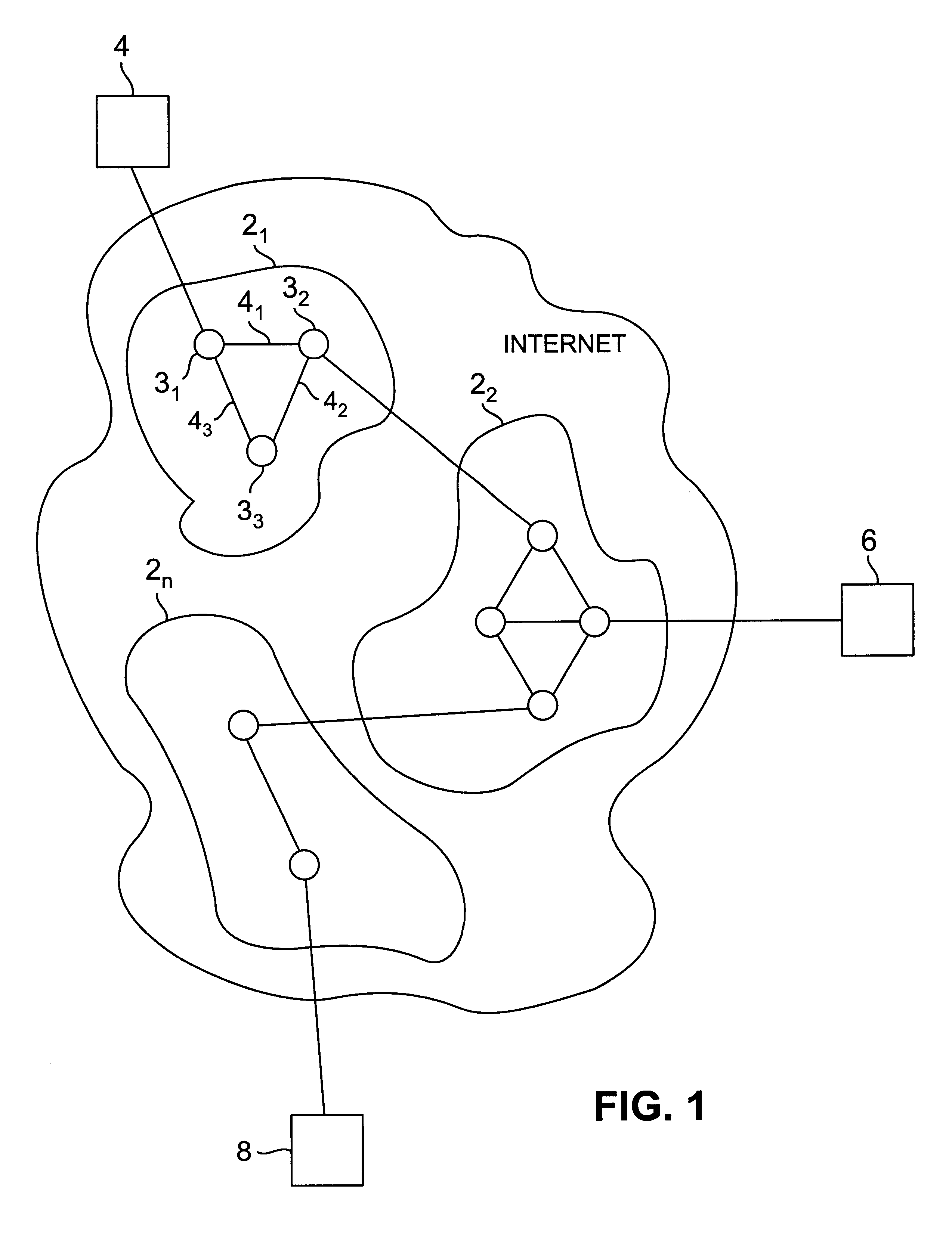
FIG. 1 shows a simplified block diagram of a packet switched network such as the Internet. The network includes a plurality of service providers 2.sub.1, 2.sub.2, . . . 2.sub.n that each control their respective network domains. For example, the domain of service provider 2.sub.1 includes routers 3.sub.1, 3.sub.2 and 3.sub.3 interconnected by links 4.sub.1, 4.sub.2, and 4.sub.3. Users communicate over the network by subscribing to a particular service provider. For example, in FIG. 1 users 4 and 6 are subscribers of service provider 2.sub.1 and 2.sub.2, respectively, and user 8 is a subscriber of service provider 2.sub.n. As employed herein a user is defined as the entity to which a network resource (i.e., bandwidth ) is allocated. A user thus may be an individual terminal or an aggregate of terminals, which has a single account with a service provider. A share denotes the amount of bandwidth that is allocated to a given user.

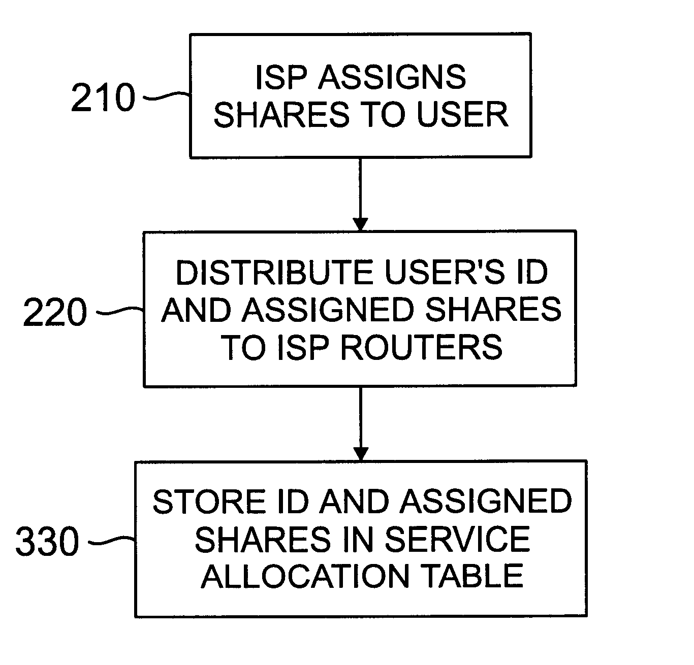
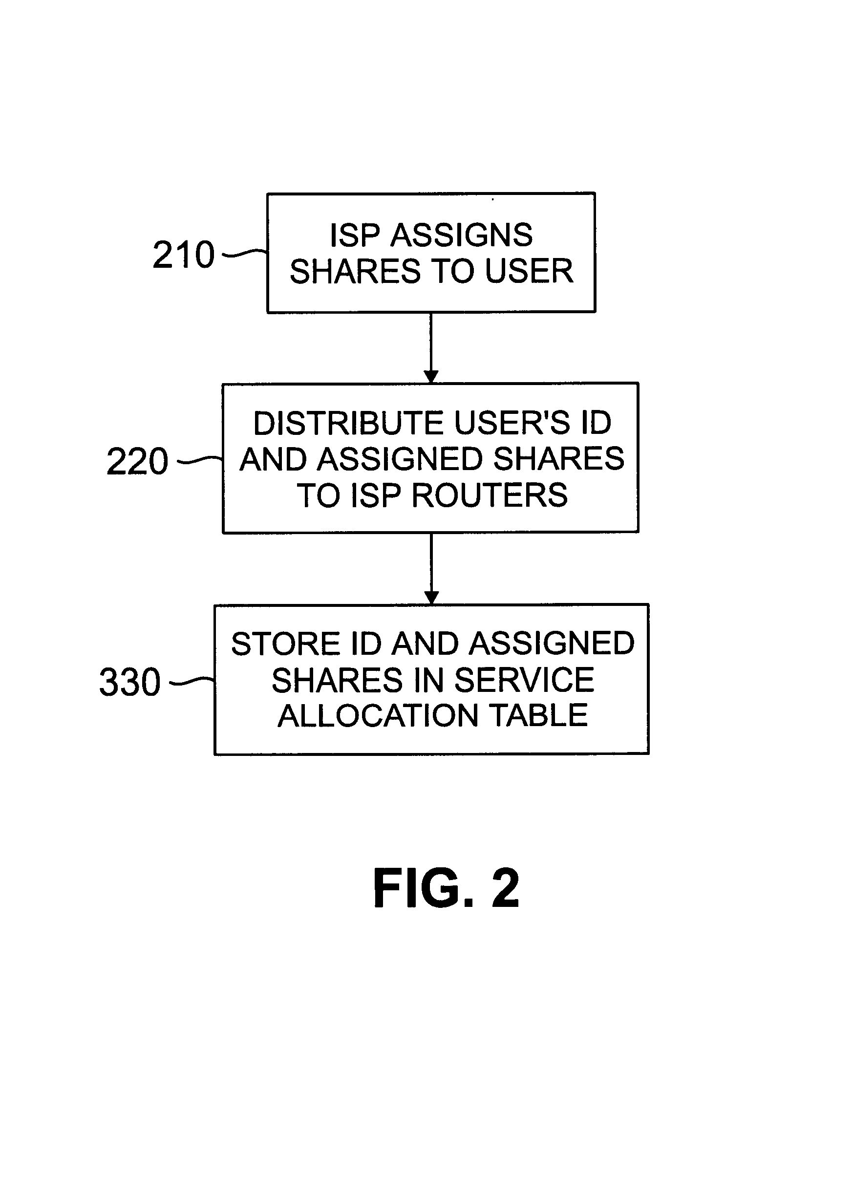
In accordance with the present invention, when each user ...


PUM


Abstract

A method is provided for allocating bandwidth to a subscriber in a service provider domain that is part of a packet switched network such as the Internet, for example. In accordance with the method, a number of shares of bandwidth are assigned to the subscriber based on an agreement between the subscriber and a service provider. A subscriber identifier and the number of shares assigned thereto are distributed to the routers in the domain of the service provider. The routers will in turn allocate bandwidth to packets they receive based on the number of shares assigned to the subscriber transmitting or receiving the packet. The subscriber may include one or more different user terminals that aggregate traffic onto a single datastream. The shares assigned to the user may denote absolute amount of bandwidth, or alternatively, may denote a relative bandwidth allocation.

Description

FIELD OF THE INVENTIONThe present invention relates generally to packet switched networks such as the Internet, and more particularly to a method for allocating bandwidth in a packet switched network to a service provider subscriber based on the cost paid by the subscriber to the service provider.BACKGROUND OF THE INVENTIONThe Internet is an example of a packet switched network in which individual packets are treated as independent datagrams on a best-effort model that are serviced on a FIFO basis. The best-effort model does not provide any form of traffic isolation among different users, however, and thus resources are shared only on the basis of how much bandwidth a user requests. Accordingly, adequate Internet functioning depends on the cooperation of hosts end systems such as TCP congestion control mechanisms. Reliance on the cooperation of the host end systems is increasingly becoming unrealistic. Inevitably, users attempt to exploit the weakness of the best-effort model to gai...

Claims


Application Information

Patent Timeline
Patent Type & Authority Patents(United States)
IPC IPC(8): H04L12/56H04L12/24H04L12/28
CPCH04L12/5695H04L41/0896H04L47/808H04L47/15H04L47/783H04L47/805H04L47/10H04L12/2856H04L47/70
Inventor WANG, ZHENG
Owner SOUND VIEW INNOVATIONS
Why Eureka
Try Eureka