Implant for osteosynthesis device with hook

a technology of osteosynthesis device and hook, which is applied in the direction of screws, nuts, bolts, etc., can solve the problems of causing numerous drawbacks, difficult use of pedicular screws, and danger for patients, and achieving the effect of easy application and us

Inactive Publication Date: 2002-05-14
SCIENTX
View PDF8 Cites 74 Cited by
  • Summary
  • Abstract
  • Description
  • Claims
  • Application Information

AI Technical Summary

Problems solved by technology

Nevertheless, it is not always possible to use pedicular screws, particularly for a vertebra at the end of the spine, or because of regulations in certain countries which allow pedicular screws to be used only under very restrictive circumstances, use thereof being considered difficult and therefore dangerous for the patient.
Nevertheless, it must be observed that using hooks gives rise to numerous drawbacks since a single hook cannot on its own provide effective mechanical fixing as can be done by a screw.
Such an assembly has the effect of securing two successive vertebrae together by moving them towards each other, but it does not provide any means for acting on either of them sep

Method used


Image

  • Implant for osteosynthesis device with hook
  • Implant for osteosynthesis device with hook
  • Implant for osteosynthesis device with hook

Examples


Embodiment Construction

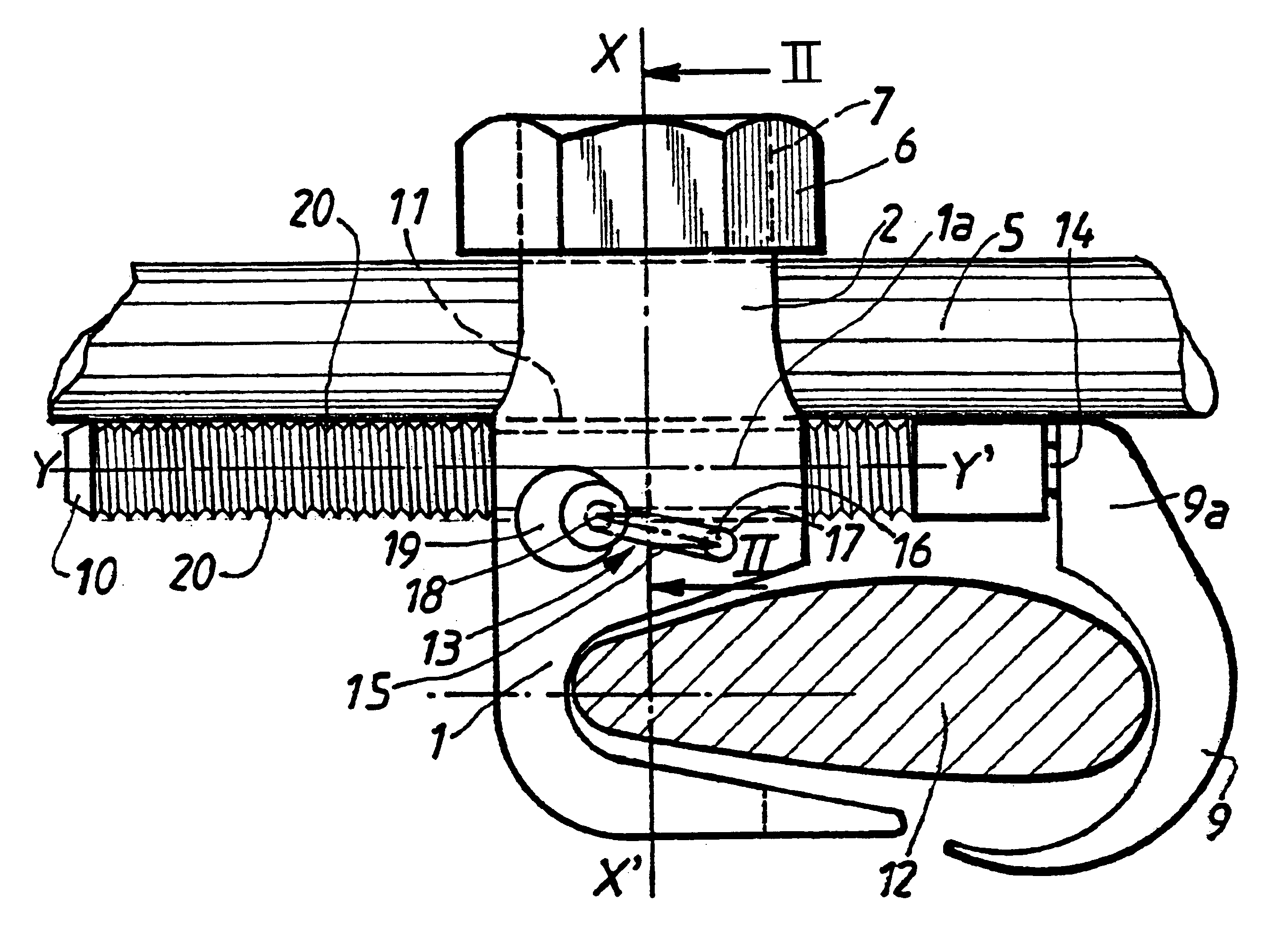
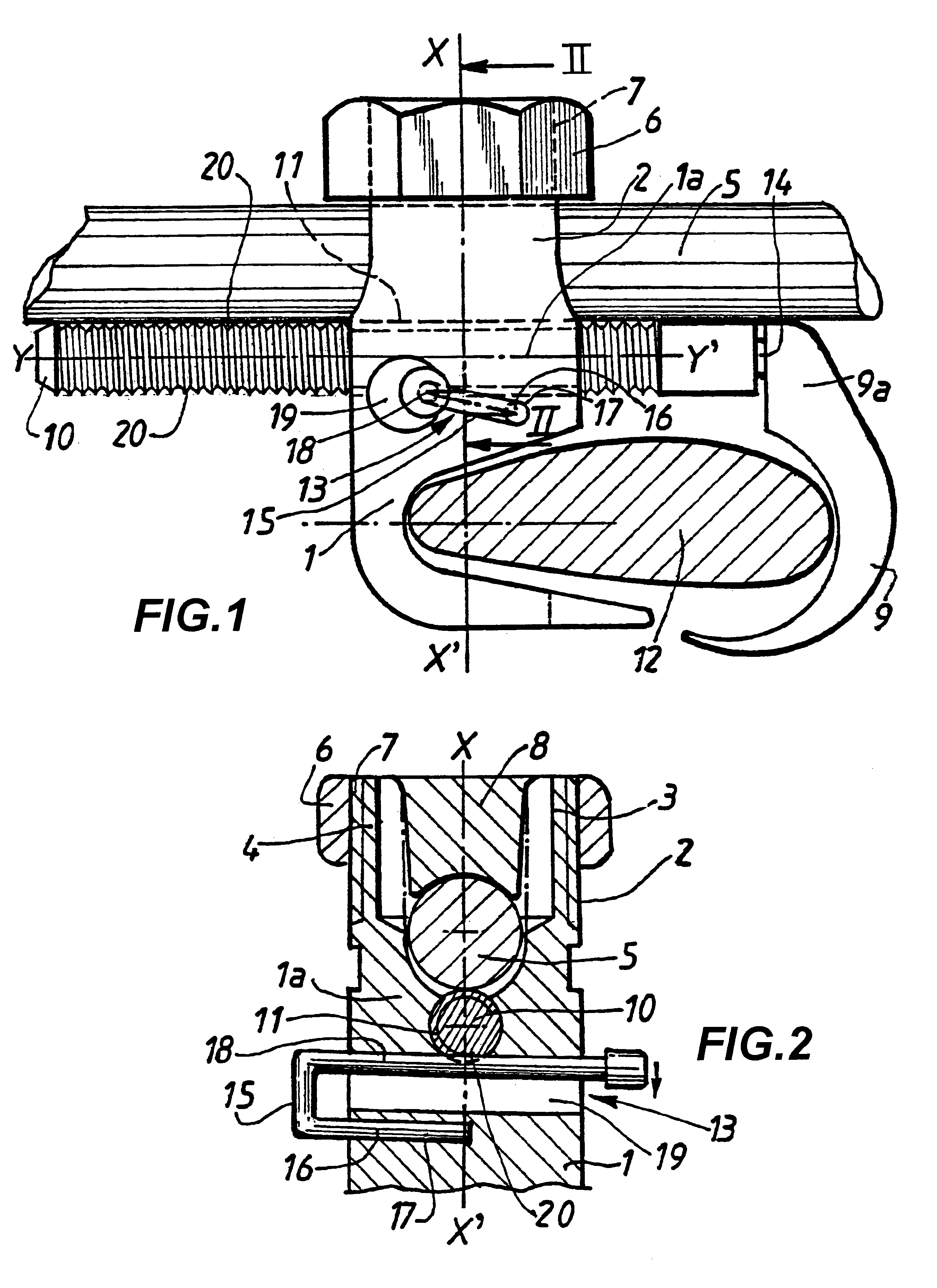
The implant shown in FIGS. 1 and 2 comprises a reference hook 1 and a counterhook 9. The hook 1 is secured to a fixing head 2 which is constituted in conventional manner by two upwardly extending members or lateral branches 3, 4 forming an open U-shaped channel and designed to receive between them a link rod 5, for the purpose of holding it fixed relative thereto by means of a tapped nut 6 suitable for being screwed onto corresponding threaded portions 7 made in the example shown on the outside walls forming portions of cylinders of the lateral branches 3, 4 of the fixing head 2.

In the embodiment shown in FIGS. 1 and 2, the nut 6 has a shoe 8 in its diametral zone, which shoe 8 is mounted so as to rotate freely and is designed to cooperate with the link rod 5 by clamping thereagainst.

The implant has free connection means between the hook 1 and the counterhook 9 enabling them to be moved freely towards each other or away from each other. The counterhook 9 faces towards the hook 1 and...


PUM


Abstract

A spinal implant device arranged to clamp at least one vertebra includes a link rod, a hook defining a central bore and secured to a fixing head, a counterhook, an elongate member, a position control device and an interconnection arrangement between the counterhook and the hook. The fixing head has a pair of upwardly extending members forming a channel configured to accommodate the link rod. A nut engages the fixing head to exert a downward force onto the link rod. The elongate member attaches at one end to the counterhook and slidably engages the central bore of the hook such that the hook and the counterhook cooperate to define a clamp. The position control device cooperates with the hook and the elongate member to selectively maintain the hook in a position relative to the counterhook.

Description

The present invention relates to an implant for an osteosynthesis device, in particular for the spine, the implant comprising a bone-anchoring device surmounted by a fixing head constituted by two upwardly extending members or lateral branches forming an open U-shaped channel and designed to receive a link rod in order to hold it in place by clamping, via a tapped nut suitable for being screwed onto corresponding threaded portions made on the walls of the lateral branches of the fixing head.PRIOR ARTIt is generally known to use hooks or pedicular screws as bone-anchoring devices. Numerous devices relate to pedicular screws which have the advantage of providing effective fixing for the implant since a pedicular screw is anchored by being screwed into a pedicle.Nevertheless, it is not always possible to use pedicular screws, particularly for a vertebra at the end of the spine, or because of regulations in certain countries which allow pedicular screws to be used only under very restri...

Claims


Application Information

Patent Timeline
IPC IPC(8): A61B17/70A61B17/58
CPCA61B17/7047A61B17/7032F16B2/12F16B39/10A61B17/70
Inventor ALBY, ALBERT
Owner SCIENTX
Why Eureka
Try Eureka