Stirling cycle engine

a technology of stirling cycle engine and stirling chamber, which is applied in the direction of machines/engines, mechanical equipment, lighting and heating apparatus, etc., can solve the problems of increased cost, longer time for machining, and inferior productivity

Inactive Publication Date: 2002-05-21
TWINBIRD CORP
View PDF10 Cites 25 Cited by
  • Summary
  • Abstract
  • Description
  • Claims
  • Application Information

AI Technical Summary

Problems solved by technology

However, for forming the cylinder integral with such mount by means of machining process, it is necessary to machine a metallic pole material that is thicker than the outer dimension of the mount, so that a considerable portion of the material becomes metal filing, thus consuming longer time for machining, leading to inferior productivity.
Further, as the outer dimension of the mount is comparatively large, a large-sized machining machine is needed, thus causing the increase of costs.
As a further conceivable method for forming the cylinder with such mount, the use of phenolic molding may be considered, which, however, requires a draft angle, and thus at least the machining inside the cylinder is needed, thus leading to a likelihood to degrade the accuracy due to thermal expansion or elastic deformation.
As is apparent from the above-mentioned, conventional manufacture of a cylinder integrally formed with a mount has had problems in respect of costs and accuracy.
In addition, as the drive mechanism retained by the mount in a stirling cycle engine reaches a high temperature, there is a risk that the heat of the drive mechanism transfers from the mount to the cylinder, and then transfers to the compression space inside the cylinder, so that the thermal expansion of the cylinder is liable to occur to thereby produce a larger clearance between the cylinder and the piston, and / or the flow of the heat into the compression space is liable to damage the stirling cycle operation itself.
Conversely, there has been a risk that the heat inside the compression space transfers to the drive mechanism via the cylinder and the mount, so that the drive mechanism is overheated.

Method used


Image

  • Stirling cycle engine
  • Stirling cycle engine
  • Stirling cycle engine

Examples


Embodiment Construction

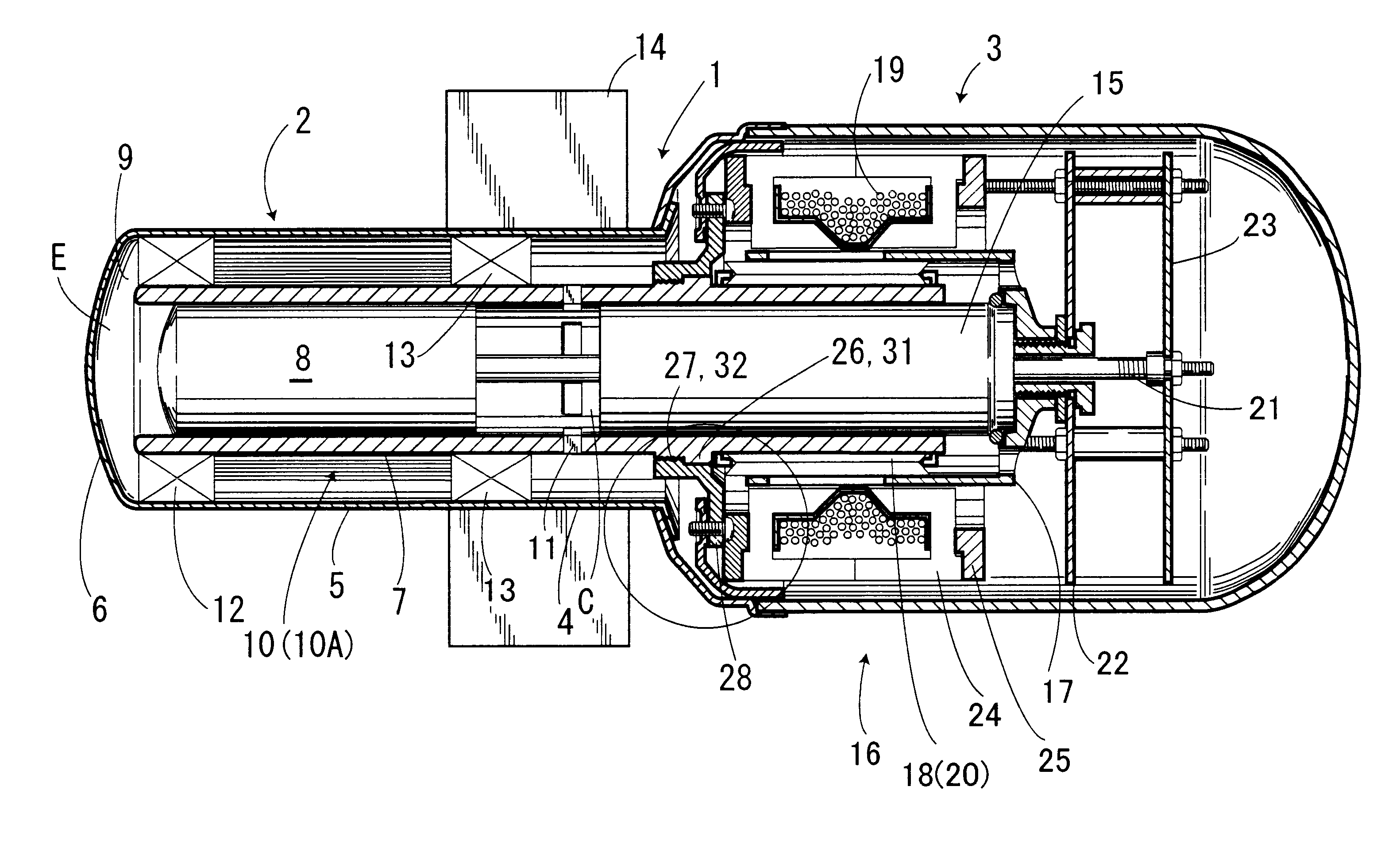
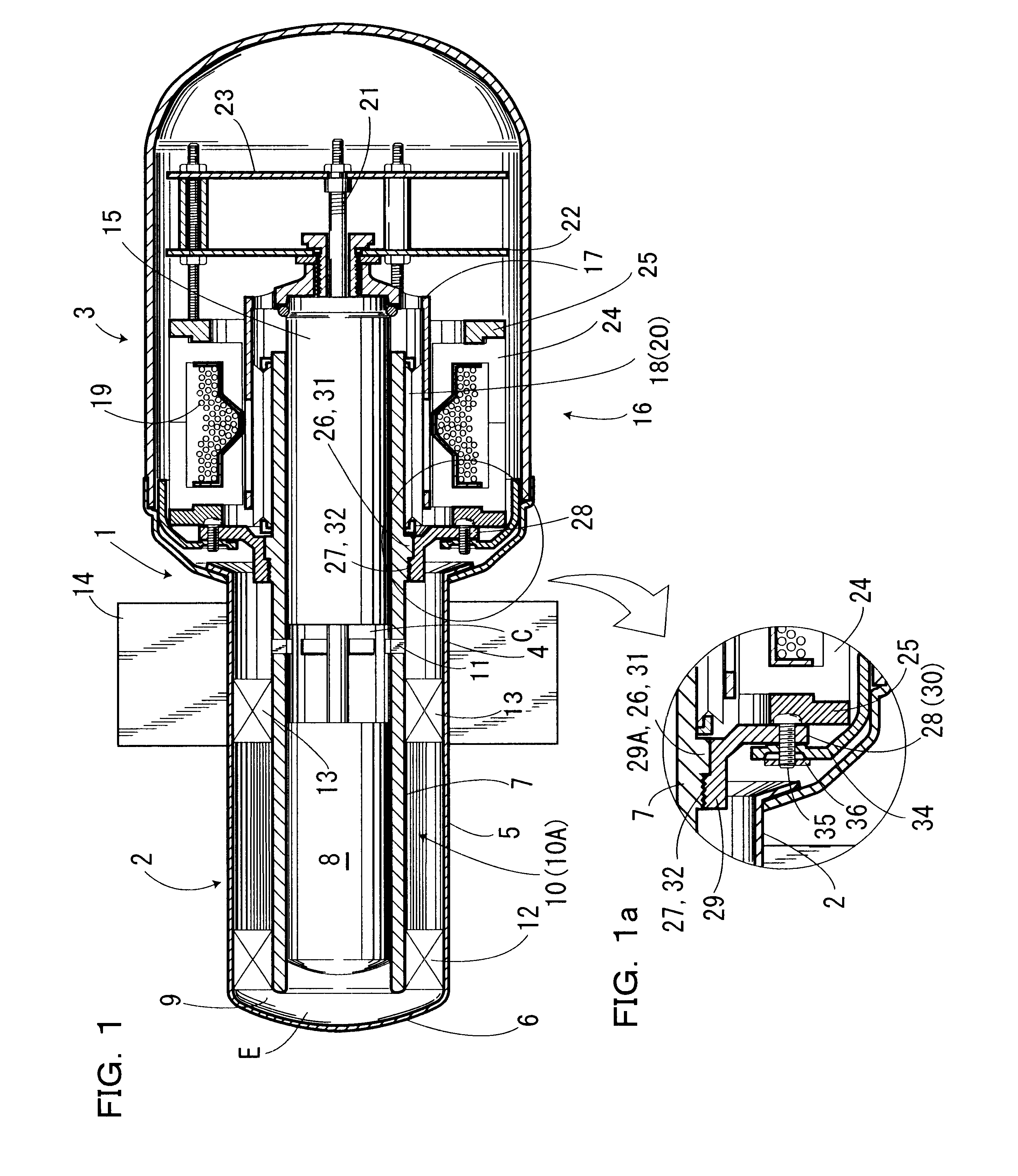
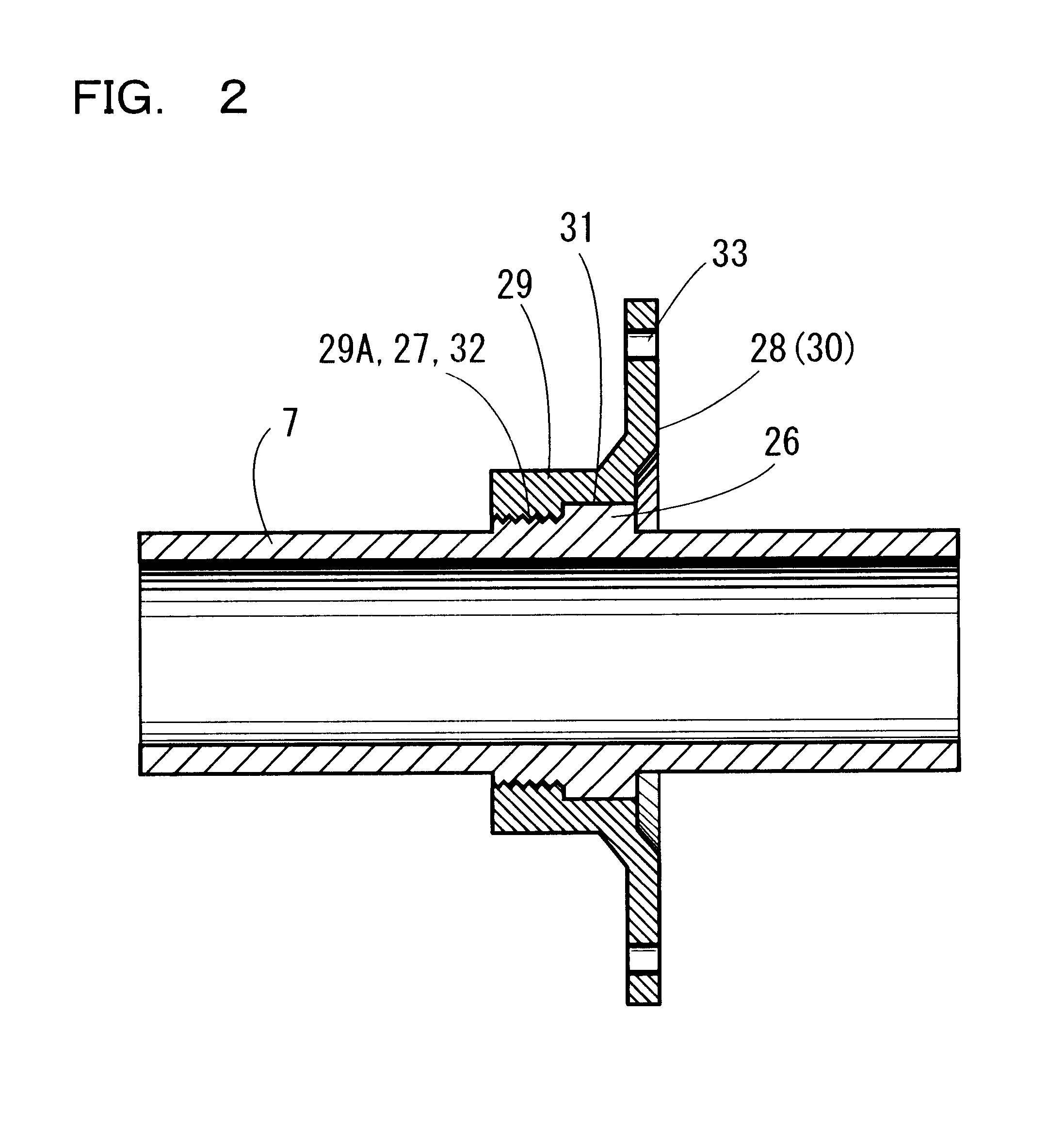
Hereinafter is described a preferred embodiment of the present invention with reference to FIGS. 1 through 4, in which reference numeral 1 designates a casing constructed of a substantially cylinder-shaped cylindrical portion 2 and a main body portion 3. The cylindrical portion 2 is made from stainless steel or the like, comprising a proximal portion 4, an intermediate portion 5 and a distal portion 6 which are integrally formed with one another.

Inside the cylindrical portion 2 is provided a cylinder 7 that is coaxially inserted into the same, extending to the main body 3. Inside the cylinder 7 is provided a displacer 8 in a manner capable of sliding in the axial direction. Between the distal end of the displacer 8 and the distal portion 6 of the cylindrical portion 2 is formed an expansion chamber E, while a space 9 provides the communication of the inside of the cylinder 7 with the outside thereof. Around the outer periphery of the cylinder 7 in the intermediate portion 5 is provi...


PUM

PropertyMeasurementUnit
heat conductanceaaaaaaaaaa
diameteraaaaaaaaaa
structureaaaaaaaaaa

Abstract

A stirling cycle engine whose cylinder, including a mount, can be easily fabricated and securely attached. The stirling cycle engine of the invention comprises a casing having a cylindrical portion 2; a metallic cylinder 7 coaxially inserted into the cylindrical portion 2 of the casing 1; a piston 15 inserted into the cylinder 7; a drive mechanism 16 for reciprocally driving the piston 15; and a mount 28 which is attached to an outer periphery of the cylinder 7 for fixing the cylinder 7 to the casing 1 and retaining the drive mechanism 16. The mount 28 is made of a material of low heat conductance, constructed separately from the cylinder 7. The mount 28 is attached to the outer periphery of the cylinder 7. Thus, the easier working thereof is resulted, so that the working time is shortened, to thereby improve productivity, and reduce working costs. Further, The heat from the drive mechanism 16 is less likely to transfer to the cylinder 7 via the mount 28.

Description

a) Field of the InventionThe present invention relates to a free-piston type stirling cycle engine, particularly to the structure of a cylinder mounted inside an apparatus body.b) Prior ArtA stirling cycle engine allows a piston to reciprocate in a cylinder in the axial direction, so that when the piston is shifted toward a displacer, a gas inside a compression chamber formed between the piston and the displacer is compressed, and then it passes through a heat dissipating fin, a regenerator and an endothermic or heat absorbing fin, to reach an expansion chamber formed between the tip end of the displacer and the tip end of a casing, thus pushing the displacer downward. On the other hand, when the piston is shifted to the opposite direction, then the inside of the compression chamber is subjected to a negative pressure, so that the gas returns from the expansion chamber to the compression chamber inside the cylinder, via the heat absorbing fin, the regenerator and the heat dissipatin...

Claims


Application Information

Patent Timeline
Patent Type & Authority Patents(United States)
IPC IPC(8): F02G1/00F02G1/043F02G1/053F16J10/00F25B9/14
CPCF02G1/043F02G2243/02F02G2243/04F02G2280/10F05C2225/08
Inventor URASAWA, HIDETOSUZUKI, KENTAROSUZUKI, TAKESHI
Owner TWINBIRD CORP
Why Eureka
Try Eureka