Remote control thermostat

Inactive Publication Date: 2002-05-28
MORGAN ARTHUR
View PDF12 Cites 134 Cited by
  • Summary
  • Abstract
  • Description
  • Claims
  • Application Information

AI Technical Summary

Problems solved by technology

This can be inconvenient at night when one is lying in their bedroom.

Method used


Image

  • Remote control thermostat
  • Remote control thermostat
  • Remote control thermostat

Examples


Embodiment Construction

of the Figures

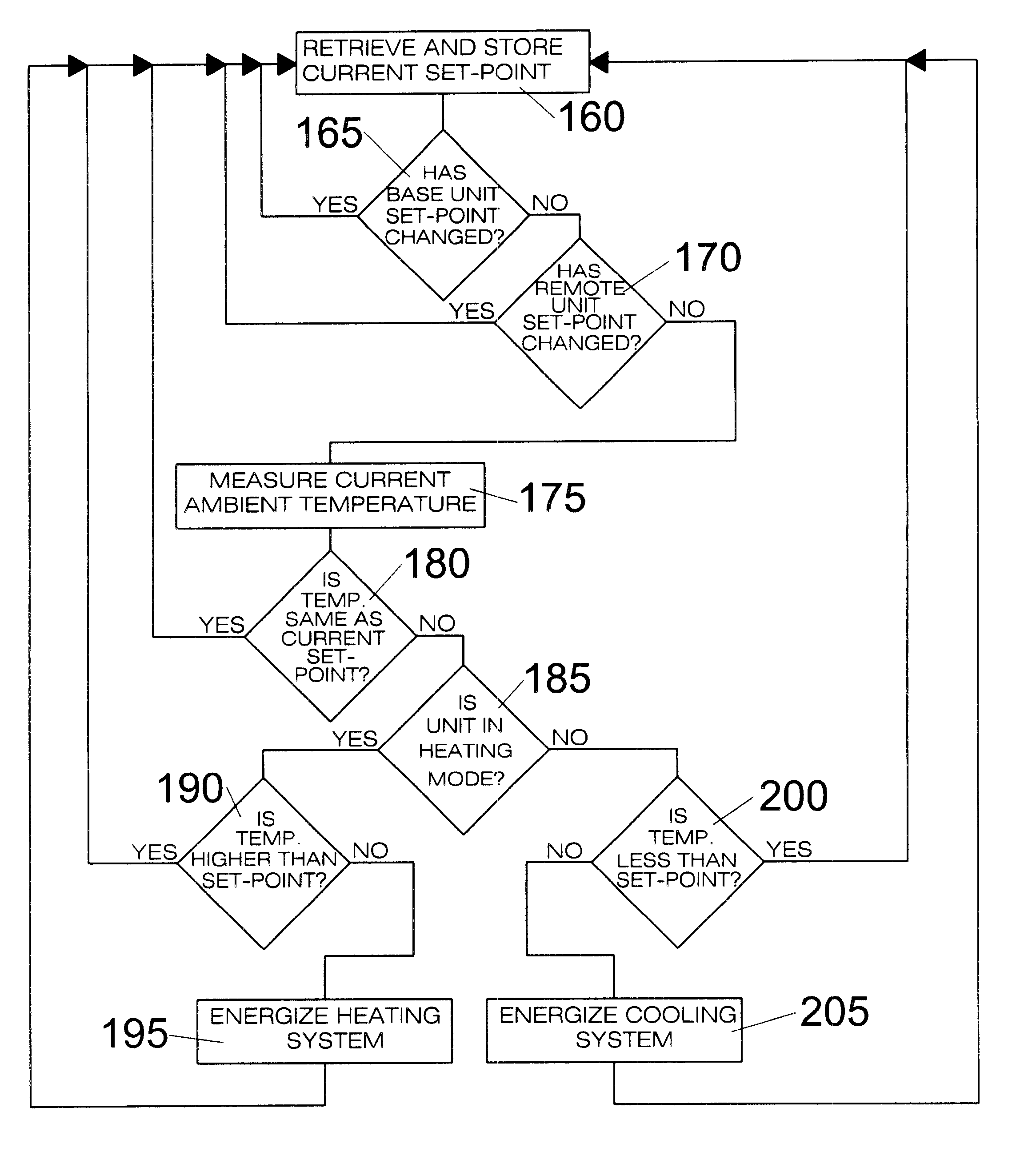
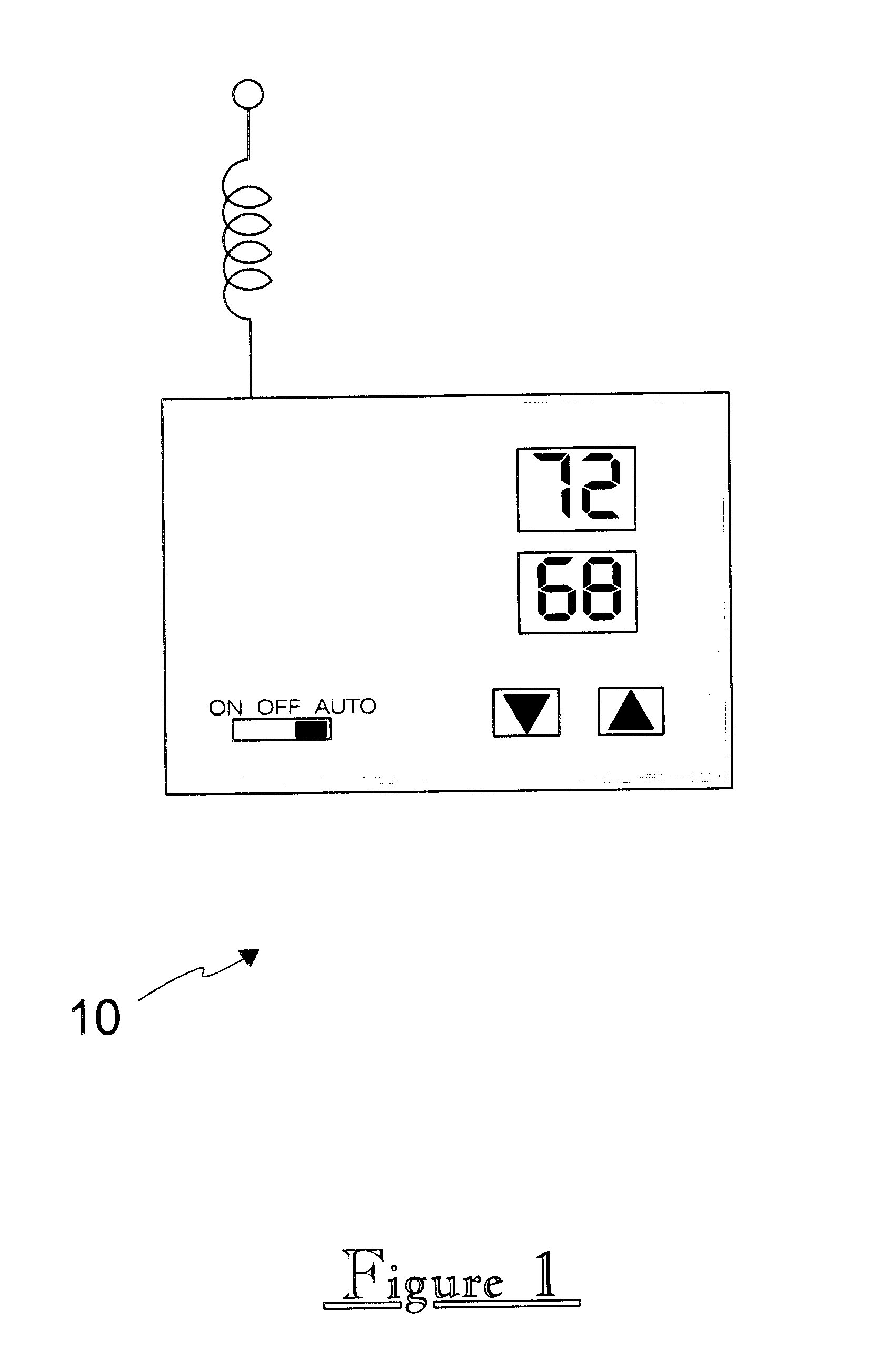
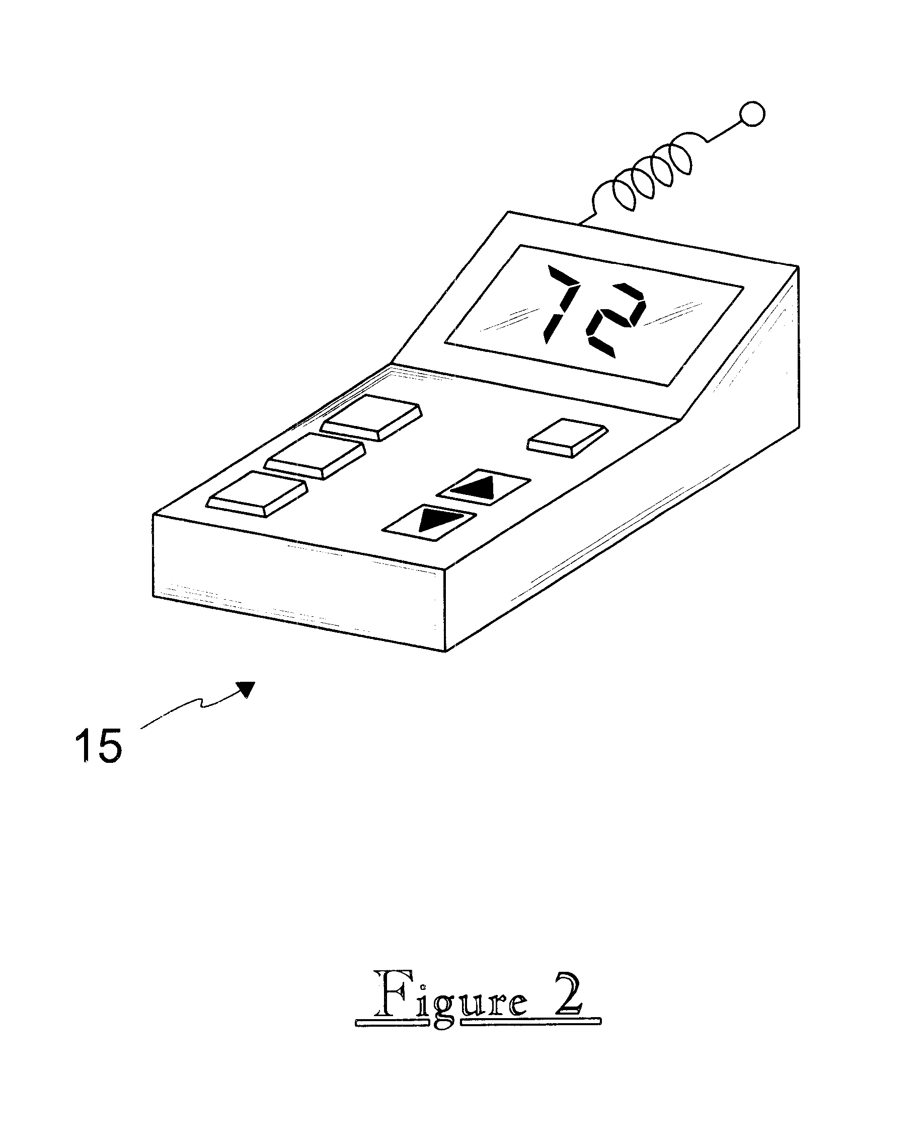
Referring now to FIG. 1, shown is a Remote Control Thermostat, according to the preferred embodiment of the present invention, comprised of a base unit 10 for mounting on the wall of a structure and a remote control unit 15 for carrying throughout the structure. Base unit 10 is an otherwise conventional thermostat typically found in the home or office with a low power transceiver coupled to the temperature sensing and regulating functions of the thermostat. Base unit 10 should be centrally located in the structure so that the local temperature reading should be representative of the temperature throughout the structure. This requires that base unit 10 be placed on a wall free from drafts from leaky doors or windows or exposed to direct sunlight. As is typical with a thermostat, base unit 10 would electronically control the temperature in the room by comparing the local temperature to a desired temperature input set into the thermostat by the user. If the local temperat...


PUM


Abstract

This invention is a remote control device to control a thermostat. The remote control works using RF transceivers in base a wall mounted base unit and a portable remote control unit, or optionally, using infrared signals much like a television remote control. The remote control has a keypad on it to allow one to select the desired temperature, or to select a temperature from one of several buttons on it corresponding to a specific temperature. This enables the user to set the temperature of a room without having to get up and manually change it.

Description

1. Field of the InventionThe present invention relates generally to temperature control and, more particularly, to a wireless remotely controlled thermostat for regulating room temperature.2. Description of the Related ArtIn the related art, there exists various devices to regulate room temperature. Typically this is done via a thermostat. The prior art includes such devices and various schemes whereby such thermostats can be remotely activated. There also exists inventions where wireless technology is used to regulate room temperature. However, the present invention has several novel features over the prior art as discussed below.Regardless of geographic location, virtually every American's home includes a climate control system for regulating the room temperature inside the dwelling. Typically consisting of a heating unit and an air conditioning unit, these devices are controlled by thermostats that switch the heating unit / air conditioner on and off in order to maintain a desired ...

Claims


Application Information

Patent Timeline
Patent Type & Authority Patents(United States)
IPC IPC(8): G05D23/19
CPCG05D23/1905
Inventor MORGAN, ARTHUR
Owner MORGAN ARTHUR
Why Eureka
Try Eureka