
Double-color infrared thermometer applied to testing of cutting temperature of machine tool

A cutting temperature and thermometer technology, applied in the field of thermometers, can solve the problems of complex focusing and aiming methods, easy failures, cumbersome debugging, etc., and achieve simple and convenient focusing and aiming, high safety and rapid response precise effect

Inactive Publication Date: 2011-11-23
SHANDONG UNIV
View PDF1 Cites 8 Cited by
  • Summary
  • Abstract
  • Description
  • Claims
  • Application Information

AI Technical Summary

Problems solved by technology

[0006] The current common two-color infrared thermometer is a single-channel dial-adjusting two-color thermometer, which shares an optical channel for signal acquisition and processing. The advantage of this kind of thermometer is that the optical structure is simple, but it needs a motor to drive the dial to rotate. High power consumption, cumbersome debugging and prone to failure; the other is a dual-channel structure, which uses a spectroscope to divide the infrared radiation emitted by the measurement target into two beams, which are irradiated on the corresponding infrared detectors through the filter that determines the main pass wavelength. In general, the ratio of the two voltages generated is calibrated to obtain the temperature. The advantage is that the operation is simple and does not require a dial and motor drive. However, due to the complexity of the focusing and aiming methods, the application is relatively seldom.

Method used


Image

  • Double-color infrared thermometer applied to testing of cutting temperature of machine tool
  • Double-color infrared thermometer applied to testing of cutting temperature of machine tool
  • Double-color infrared thermometer applied to testing of cutting temperature of machine tool

Examples


Embodiment Construction

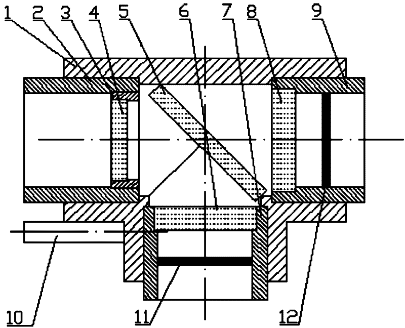
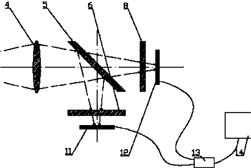
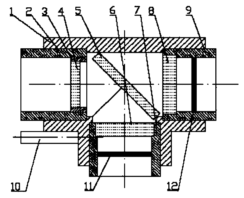
[0017] The structure of the two-color infrared thermometer of the present invention is as follows: figure 1 with figure 2 As shown, it includes a housing 1 , a laser sight 10 , a focusing tube 2 , a convex lens 4 , a beam splitter 5 , an optical filter, an infrared detector, a processor 13 and a display 14 . The housing 1 is a three-way pipe structure. A laser sight 10 is mounted on the casing 1 . The focus tube 2 is installed in one of the two through ports in the shell 1, and is screwed to the shell 1. The inside of the focus tube 2 is equipped with a convex lens 4 through the lens sleeve 3, and the measurement can be adjusted by rotating the focus tube 2. distance. The beam splitter 5 is arranged inside the casing 1 and forms an angle of 45° with the convex lens 4 . A filter sleeve 7 and a filter sleeve 9 are installed in the other two openings of the housing 1 respectively, and the axes of the filter sleeve 7 and the filter sleeve 9 are vertical. The inner ends of th...


PUM


Abstract

The invention provides a double-color infrared thermometer applied to testing of cutting temperature of a machine tool. The double-color infrared thermometer comprises a shell, a laser sighting device, a focusing cylinder, a convex lens, a beam splitter, optical filters, infrared detectors, a processor and a display; the shell has a structure of a three-way pipe; the laser sighting device is arranged on the shell and is positioned below the focusing cylinder; the focusing cylinder is arranged in one of two straight ports in the shell; the convex lens is arranged in the focusing cylinder; the beam splitter is arranged in the shell and an included angle of 45 degrees is formed between the beam splitter and the convex lens; the optical filters are arranged in other two openings of the shell; the infrared detectors are arranged outside the optical filters; the distances between the optical filters of the two openings of the shell and the infrared detectors are equal; meanwhile, the distances between two optical filters and the geometric center of the beam splitter are equal; and two infrared detectors are connected with the processor and the display is connected with the processor. The double-color infrared thermometer is high in measurement efficiency, high in safety performance and low in power consumption, has a simple structure and can continuously test temperature and store and export data.

Description

technical field [0001] The invention relates to a thermometer used for testing the cutting temperature of machine tools, belonging to the technical field of temperature testing. Background technique [0002] In the machinery manufacturing industry, most of the mechanical parts are currently made by cutting. Except for a small amount of cutting heat dissipating to the surrounding medium, the rest is transmitted into the tool, chips and workpiece, causing the tool, workpiece and machine tool to heat up, which will accelerate tool wear, cause thermal deformation of the workpiece, and even cause thermal deformation of the machine tool in severe cases. Therefore, it is very important to measure the cutting temperature when conducting research on cutting theory, cutting tool cutting performance test and processing performance test of processed materials. [0003] The current measurement of cutting temperature is mainly through contact measurement methods such as thermocouples, wh...

Claims


Application Information

Patent Timeline
IPC IPC(8): G01J5/00
Inventor 刘战强王大振万熠任小平
Owner SHANDONG UNIV
Learn More