Direct current motor

a direct current motor and motor technology, applied in the direction of dynamo-electric components, electromagnetic interference suppression, association for rectification, etc., can solve the problem that the noise generated in the motor drive operation cannot be sufficiently eliminated

Inactive Publication Date: 2002-05-28
MITSUBISHI ELECTRIC CORP
View PDF5 Cites 28 Cited by
  • Summary
  • Abstract
  • Description
  • Claims
  • Application Information

AI Technical Summary

Problems solved by technology

However, because the conventional direct current motor has the above-described structure, there is a problem that the noise generated in the motor drive operation cannot be sufficiently eliminated.

Method used


Image

  • Direct current motor
  • Direct current motor
  • Direct current motor

Examples


first embodiment

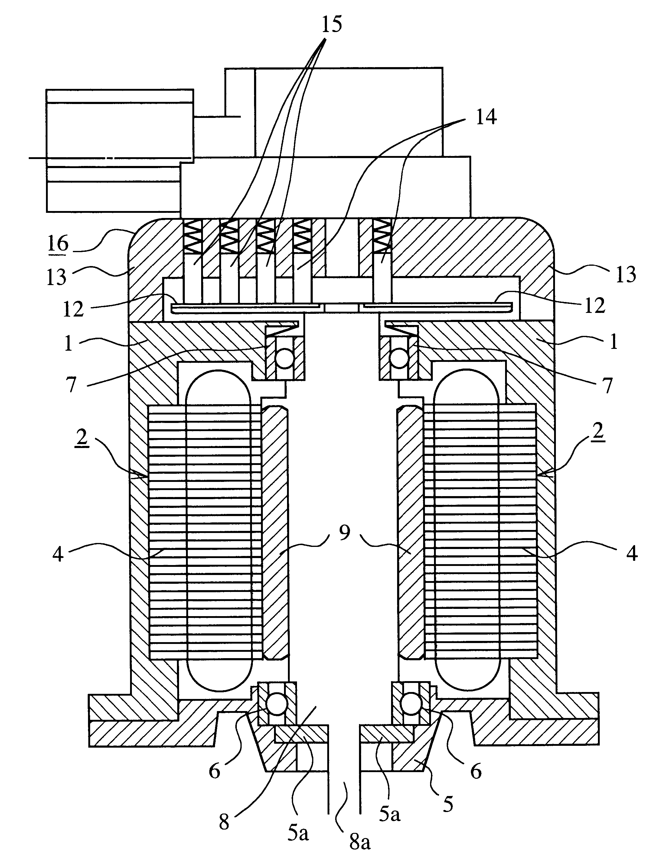
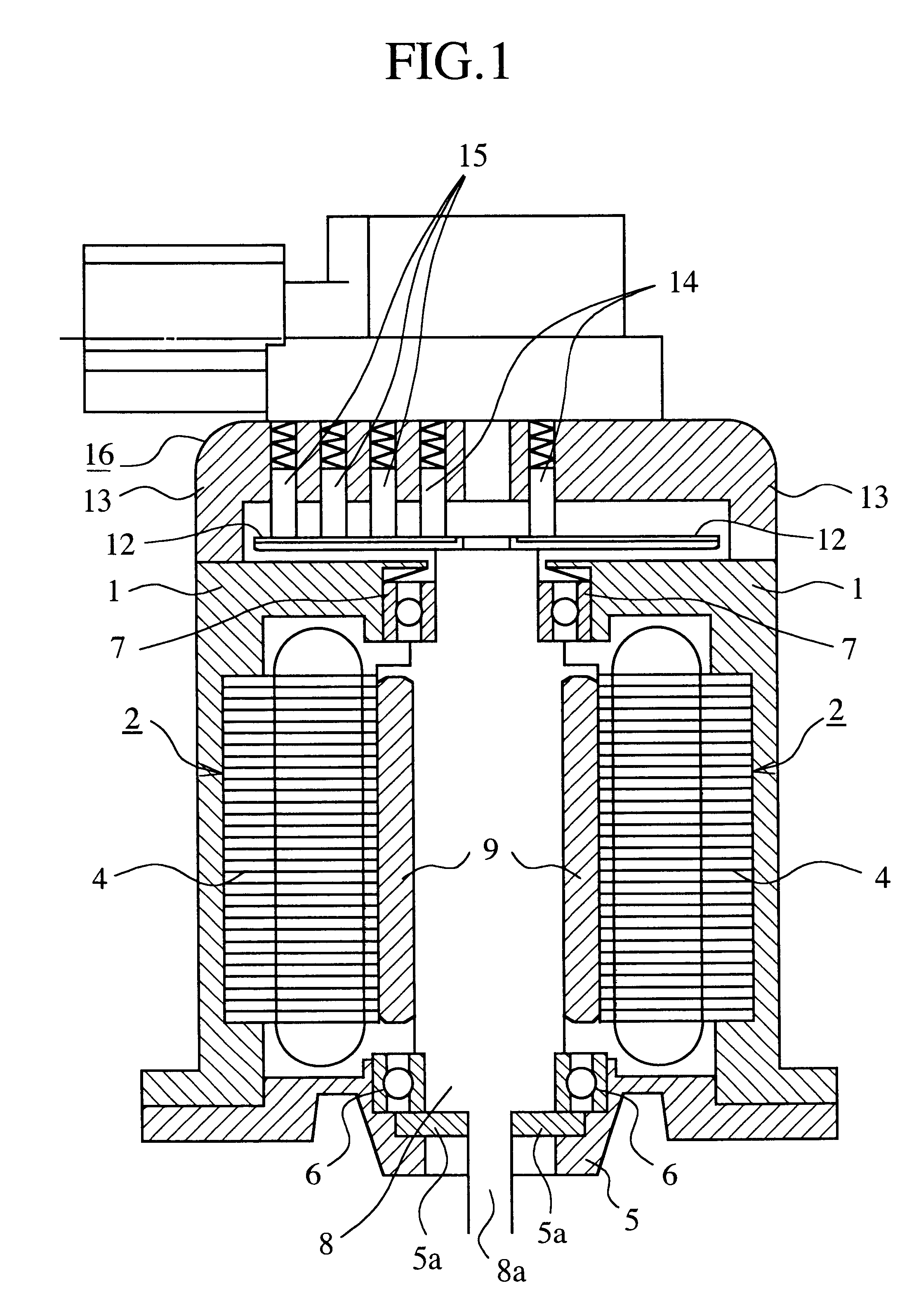
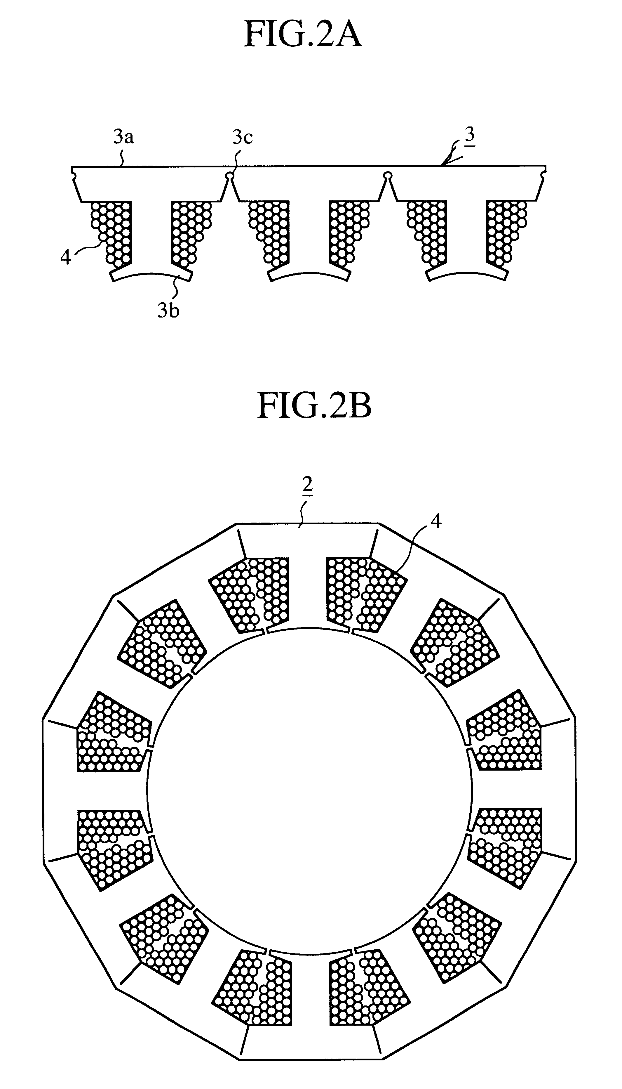
FIG. 1 is a sectional view showing the structure of a direct current motor according to the present invention. FIG. 2A and FIG. 2B are plan views of the direct current motor shown in FIG. 1 and show a manufacturing method of a stator of the direct current motor. FIG. 3 is a diagonal view showing the structure of a commutator and a plurality of strip rings of a current carrying device shown in FIG. 1. FIG. 4 is a plan view showing a plurality of noise eliminating members arranged at prescribed positions of a stator core of the direct current motor shown in FIG. 1. FIG. 5 is a sectional view of connection between each noise eliminating member shown in FIG. 4 and a motor brush holding plate arranged in the stator core as an example. FIG. 6 is a sectional view showing a current flow in the current carrying device of the direct current motor shown in FIG. 1.

In FIG. 1 to FIG. 6, a numeral number 1 indicates a motor case formed of resin material. 2 indicates a stator integrally formed with...

embodiment 2

FIG. 7 is a sectional view of connection between each noise eliminating member shown in FIG. 4 and the corresponding motor brush holding plate arranged in the stator core as another example. The constitutional elements of a direct current motor according to a second embodiment, which are the same as or equivalent to those according to the first embodiment, are indicated by the same reference numerals as those of the first embodiment, and additional description of the constitutional elements is omitted.

second embodiment

As shown in FIG. 7, features of a direct current motor are in that the connection terminals 24 of the noise eliminating members 23 are respectively caulked at caulking portions 21d of the brush holding plates 21 to fix the connection terminals 24 to the brush holding plates 21.

Accordingly, in the second embodiment, because the connection terminals 24 of the noise eliminating members 23 are caulked and fixed, not only the noise can be efficiently and reliably eliminated, but also the fixing operations of the noise eliminating members 23 can be easily performed, a manufacturing efficiency of the direct current motor can be heightened, and a manufacturing cost of the direct current motor can be reduced.

In the first and second embodiments, the noise eliminating members 23 are arranged in three of the four brush holding plates 21. However, it is applicable that one noise eliminating member 23 be arranged in each pair of brush holding plates 21 adjacent to each other. In this case, noise...


PUM


Abstract

A direct current motor according to the present invention is provided with a stator 2 in which coils 4 corresponding to N phases are arranged almost at equal intervals in a circle-circumferential direction of stator cores 3, a rotor 8 in which a plurality of permanent magnets 9 are respectively arranged at positions corresponding to the coils 4 of the stator 2, and a current carrying device, having a commutator 11, for commutating direct current supplied from a power source to N-phase current in cooperation with the rotor 8 and carrying the N-phase current to each coil of the stator 2. In the internal space of the current carrying device, a plurality of noise eliminating members 23 connected with a plurality of brush holding plates corresponding to the coil phases are arranged.

Description

1. Field of the InventionThe present invention relates to a direct current motor appropriate to an exhaust gas recycle valve device in which the direct current motor is used for a vehicle height adjusting device or an exhaust gas recycle system mounted in a vehicle.2. Description of Related ArtPublished Unexamined Japanese Patent Application No. H11-168851 (1999) discloses a known direct current motor. This type direct current motor is principally composed of a rotor, a stator functioning as a case for surrounding the rotor and a commutator. Coils are arranged in the rotor, a plurality of permanent magnets arranged at equal intervals are tightly fitted to an inner peripheral face of the rotor, and the commutator can be coaxially rotated together with the rotor. Also, noise eliminating parts such as condensers, varistors and the like are arranged to eliminate noise generated in a motor drive operation. For this reason, these components are arranged between terminals functioning as an...

Claims


Application Information

Patent Timeline
Patent Type & Authority Patents(United States)
IPC IPC(8): H01R39/00H02K11/02H01R39/06H02K23/62H01R39/64
CPCH01R39/06H02K23/62H02K11/026H01R39/64H02K5/22
Inventor FUJITA, YOUICHIMIYOSHI, SOTSUOMIYAKE, TOSHIHIKOKAWAMURA, SATOSHI
Owner MITSUBISHI ELECTRIC CORP
Why Eureka
Try Eureka