Drawing candidate line segments extraction system, drawing candidate line segments extraction method, solid model synthesis system, and solid model synthesis method

a technology extraction methods, applied in the field of drawing candidate line segments extraction systems, drawing candidate line segments extraction methods, solid model synthesis systems, etc., can solve the problems of large number of candidate line segments of the side view, insufficient two-dimensional drawings, and insufficient synthesis of solid models

Inactive Publication Date: 2002-06-04
IBM CORP
View PDF5 Cites 5 Cited by
  • Summary
  • Abstract
  • Description
  • Claims
  • Application Information

AI Technical Summary

Benefits of technology

FIG. 13 explains the conventional method for extracting candidate line segments for a side view from a top view and a front view which are made by projecting a solid;
FIG. 14 shows an example in which a side view was made from relatively complicated top and front views based on the conventional method.

Problems solved by technology

In this case, two-dimensional drawings are insufficient, and a solid, three-dimensional model is required.
Consequently, to evaluate the functions of an object of design on a computer, it is necessary to synthesize a solid model from such plurality of drawings in which the design information is held, but the synthesis of a solid model takes tremendous time and labor.
However, such a conventional candidate line segment extraction method caused the inconvenience that the number of the candidate line segments of the side view became considerably large and the time taken for the process for synthesizing a solid model greatly increased.

Method used


Image

  • Drawing candidate line segments extraction system, drawing candidate line segments extraction method, solid model synthesis system, and solid model synthesis method
  • Drawing candidate line segments extraction system, drawing candidate line segments extraction method, solid model synthesis system, and solid model synthesis method
  • Drawing candidate line segments extraction system, drawing candidate line segments extraction method, solid model synthesis system, and solid model synthesis method

Examples


embodiment

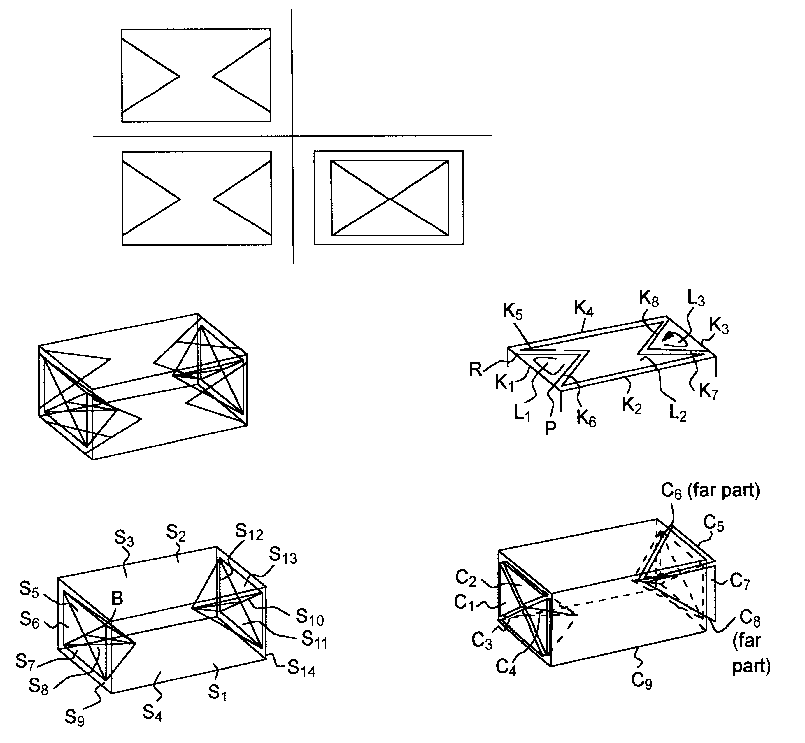
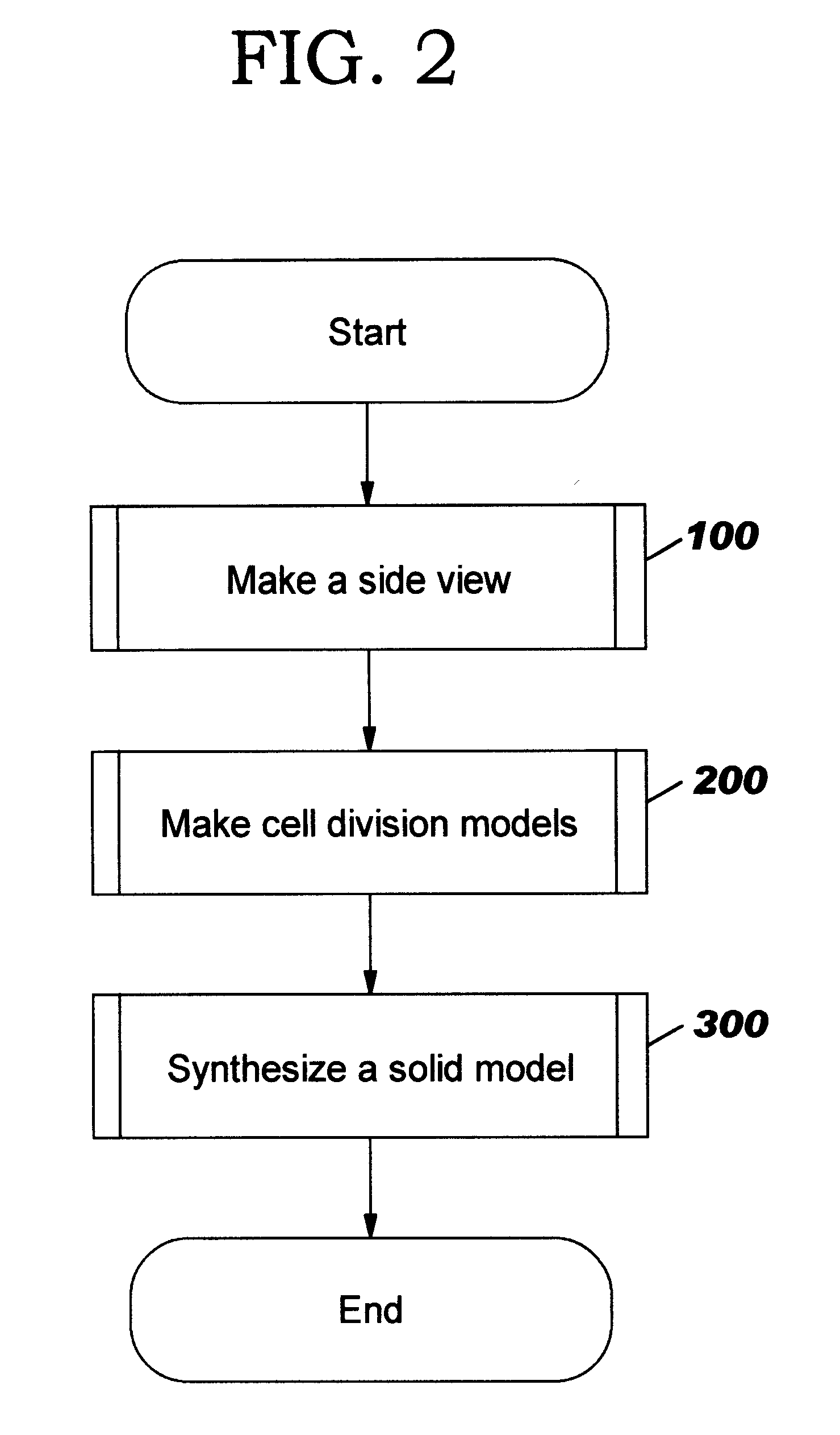
An embodiment of the present invention will now be described. The present embodiment extracts candidate line segments formed from two views, a front view and a top view, which are made by projecting a solid onto two planes perpendicular to each other, makes a side view from the extracted candidate line segments, and based on these three views, synthesizes a solid model for the solid.

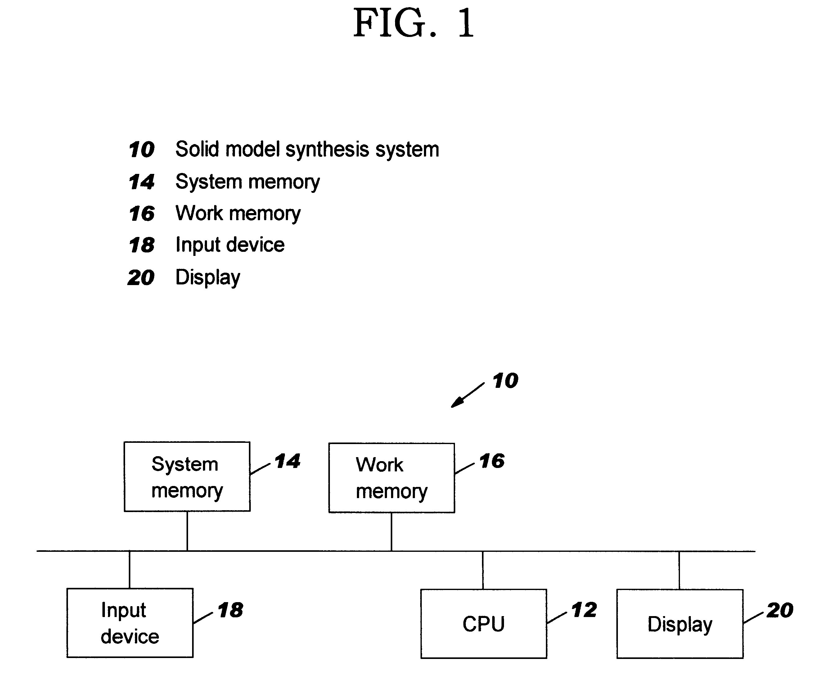
As shown in FIG. 1, a solid model synthesis system 10 comprises a CPU 12, a system memory 14, a work memory 16, an input device 18, and a display 20, which are interconnected through a bus. In the system memory 14, a later described control routine executed by the CPU 12 is stored. Also, in the work memory 16 stores various data on the drawings which are previously input from the input device 18 consisting of an image scanner, a keyboard, and the like, for instance, the coordinate data of the start and end points of line segments of the two views.

The solid model synthesizing routine of the present embodi...


PUM


Abstract

The two-dimensional coordinates of a vertex are extracted in each of a top view and front view and, if their X-coordinates are equal to each other, the combination of their Y-coordinate values is determined to be the two-dimensional coordinates of a candidate vertex in a side view. Then, candidate line segments for the side view are extracted from the line segments connecting two candidate vertices, excepting not only those line segments for which no corresponding line segment exists in the top and front views, but a so those line segments for which corresponding horizontal or vertical line segments exist in the top and front views, and which a e not horizontal or vertical in the side view.

Description

The present invention is related to a system and method for candidate line segment generation, and to a solid model synthesis system and method. More particularly, the invention is a system for extracting candidate line segments and a candidate line segment generation method for extracting, from a first drawing and a second drawing of a solid (which are made by projecting a solid onto two planes perpendicular to each other) candidate line segments for forming a third drawing made by projecting the solid onto a plane perpendicular to each of the two planes, and to a solid model synthesis system and a solid model synthesis method for synthesizing a three-dimensional solid model, from the first and second drawings and from the third drawing made by the candidate line segments.DESCRIPTION OF THE RELATED ARTMany manufacturers have been making drawings for design, and have been accumulating design information in the form of drawings.However, recently, the improvement of simulation techniq...

Claims


Application Information

Patent Timeline
Patent Type & Authority Patents(United States)
IPC IPC(8): G06T17/10G06F17/50G06T15/00G06T19/00
CPCG06T17/10
Inventor MASUDA, HIROSHIMATSUZAWA, HIROFUMI
Owner IBM CORP
Why Eureka
Try Eureka