Process for making a multi-layered solid surface article

Inactive Publication Date: 2002-06-11
SURFACE TECH
View PDF27 Cites 31 Cited by
  • Summary
  • Abstract
  • Description
  • Claims
  • Application Information

AI Technical Summary

Problems solved by technology
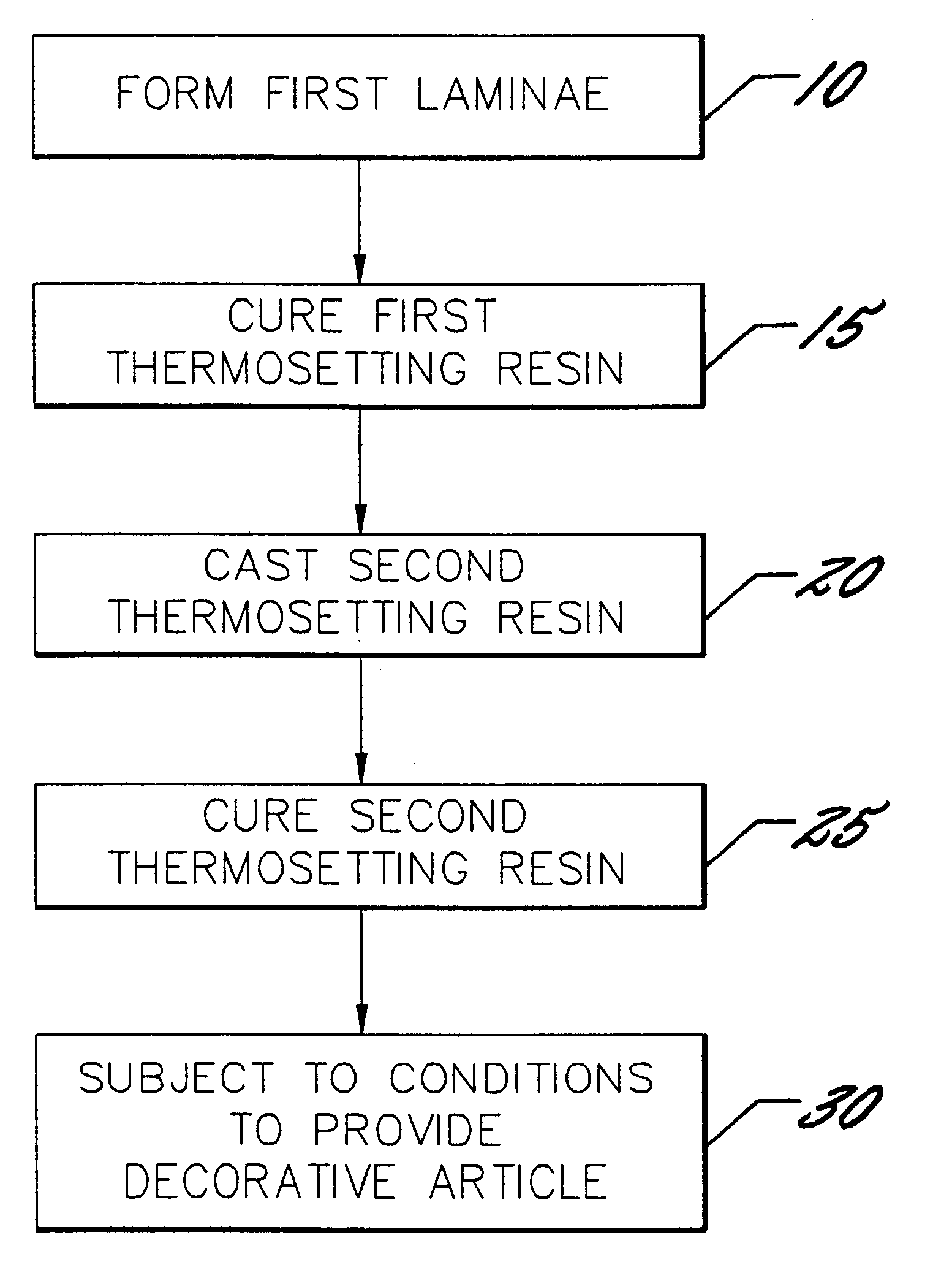
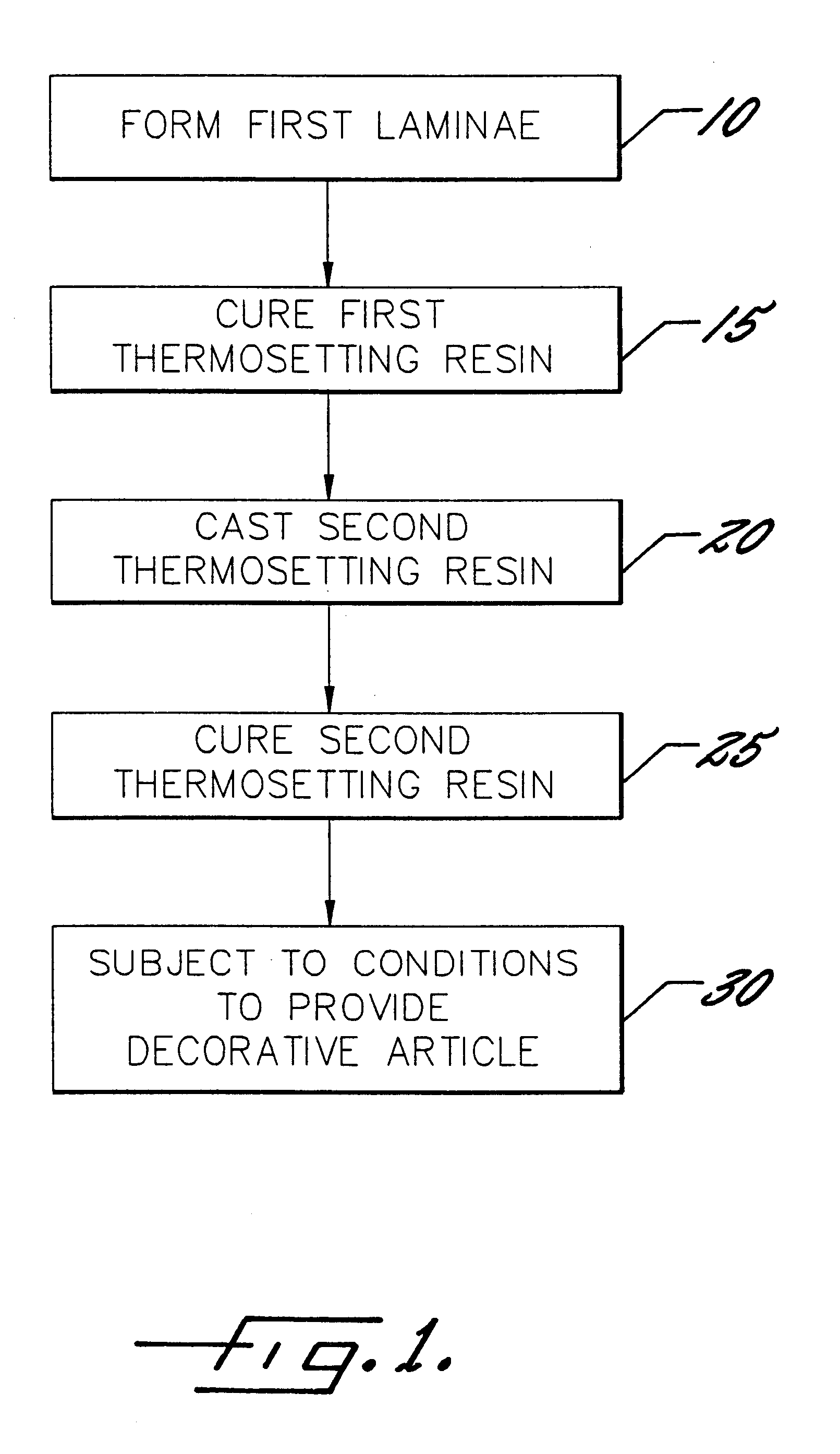
The limitation of these solid surface materials and the processes for making them are that in order to provide other decorative effects such as patterns, inlays or grooves simulating grout or seams, a highly skilled machinist must manually cut the effect into the solid surface material followed by casting a resin having a contrasting color, for example, into the cut portion to provide the decorative effect.
This is time consuming and often is not carried out by the manufacturer but by a craftsman in the field.
Moreover, such a technique has limited ability for mass production of solid surface materials.

Method used


Image

  • Process for making a multi-layered solid surface article
  • Process for making a multi-layered solid surface article
  • Process for making a multi-layered solid surface article

Examples


example 2

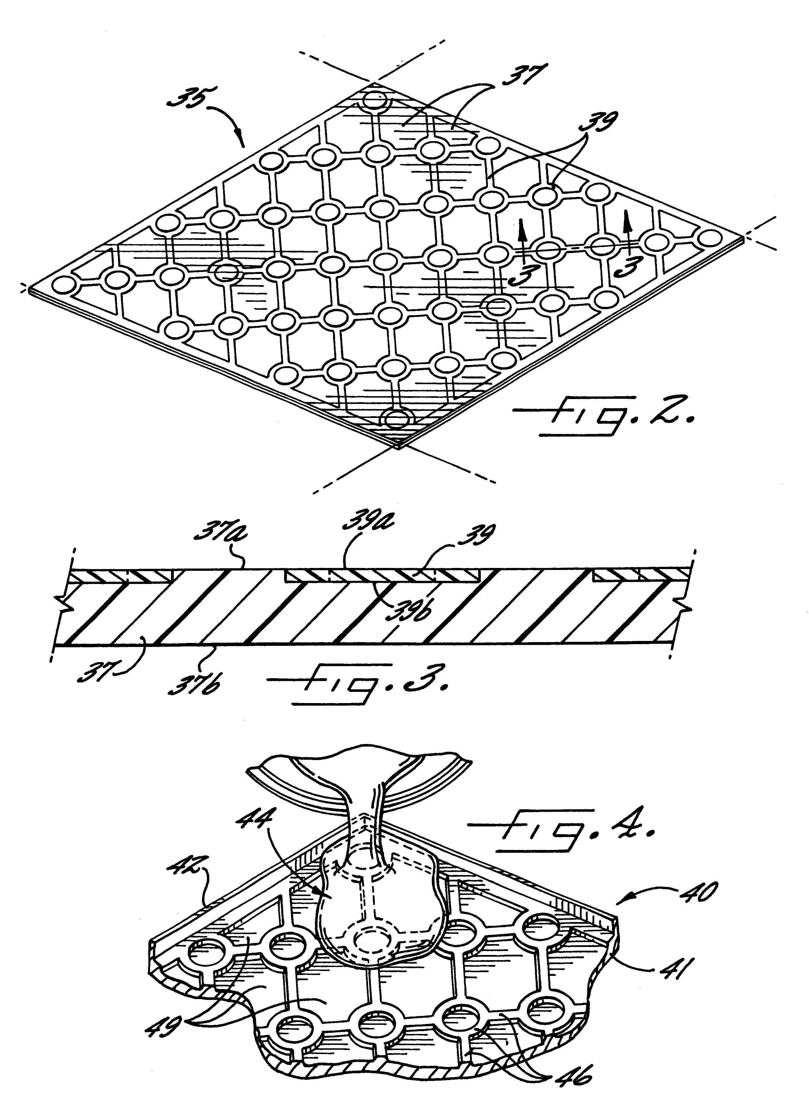
A first lamina was produced as in Example 1 above using the same thermosetting resin system. A second lamina was prepared by partially filling the recessed portions in the first lamina to create a decorative article having first and second laminae simulating ceramic tiles surrounded by grout. This was done by spraying Seagrave F.921301 omniplet steel grey granite simulation materials (Seagrave Industrial Coatings, Carlstadt, N.J.) through a Binks #7 spray gun, and partially filling the voids. The sanded surface then leaves a tile and recessed grout appearance.

example 3

A first lamina was produced as in Example 1 above except that the resin system mixture comprised the following (percents are given by weight based on total weight of resin): 66% Aluminum trihydrate (available from R J Marshall Company, 26776 W. Twelve Mile Road, Southfield, Mich. 48034 as Filler # DF40); 34% cobalt promoted ISONPG resin (available from Reichhold Chemical Company, Research Triangle Park, N.C., as PolyLite # 31210); 2% TiO.sub.2 pigment (available from HK Research, 908 Lenoir Road, Hickory, N.C. 28603); 2% MEKP catalyst (available from ATOCHEM, Military Road, Buffalo, N.Y. 14240 as LUPERSOL DDM-9).

The first lamina was allowed to cure to a firm gel stage for 20 minutes and then subjected to a pressure of 50 psi for 1 hour. The second lamina was created following the steps of Example 1 or Example 2 above.

example 4

A casting part was prepared based on an interlocking pattern of irregular pebble-like form. The casting part was cut from a solid high density polyethylene sheet to a depth of 0.070". The casting part was machined with a CNC Router from a scanned piece of art work. The following polyester compound was prepared (percents are given by weight based on total weight of resin): 50% ISONPG Resin (available from HK Research, 908 Lenoir Road, Hickory, N.C. 28603 as # HKR0050); 50% ATH Filler (available from R J Marshall Company, 26776 W. Twelve Mile Road, Southfield, Mich. 48034 as Filler # DF40); 0.6% off white pigment (available from HK Research, 908 Lenoir Road, Hickory, N.C. 28603); 1% MEKP catalyst (available from Atochem, Military Road, Buffalo, N.Y. 14240, as LUPERSOL DDM-9).

This mixture was poured into casting part and allowed to cure for one hour. A second compound with the same chemistry, but with a brown pigment was brushed over the recessed portions in the first lamina created by...


PUM

PropertyMeasurementUnit
Pressureaaaaaaaaaa
Angleaaaaaaaaaa
Angleaaaaaaaaaa

Abstract

A process for producing a decorative article having a face layer of multiple laminae is disclosed. A first curable resin is formed into a first lamina having a face layer with a relief and a substantially planar back layer. The first resin is cured and then a second curable resin is-applied to the face layer of the first lamina. The second resin is cured to produce a second lamina and the first and second laminae are then sanded to provide a decorative article of manufacture having a substantially planar face layer.

Description

FIELD AND BACKGROUND OF THE INVENTIONThe present invention relates to a process for making a decorative article, and more particularly a solid surface decorative article.Solid surface articles have been available for over twenty years. The term "solid surface" relates to a material that has substantially the same physical and aesthetic properties throughout its thickness. Thus, if the surface of the material is sanded or planed, a substantially identical aesthetic is found. Solid surface materials are typically molded out of various thermosetting resins such as unsaturated polyester resins. Various aesthetics are produced such as solid color, marbleized color (see, for example, U.S. Pat. No. 5,166,230 to Stecker) and particulate dispersion (see, for example, U.S. Pat. No. 4,959,401 to Bellasalma et al.).The limitation of these solid surface materials and the processes for making them are that in order to provide other decorative effects such as patterns, inlays or grooves simulating...

Claims


Application Information

Patent Timeline
IPC IPC(8): B29C41/02B29C41/22B29C41/20B44C5/00B44C3/00B44C1/22B44C5/04B29C39/02B44C3/02
CPCB29C41/20B29C41/22B44C1/222B44C3/005B44C5/0453B44C3/00Y10S264/57
Inventor STECKER, WILLIAM M.
Owner SURFACE TECH
Why Eureka
Try Eureka