
Method and apparatus for distance measurement

a technology of distance measurement and distance measurement, applied in the direction of measuring devices, instruments, reradiation, etc., can solve the problems of limiting the distance over which the device can be used or the speed of respons

Inactive Publication Date: 2002-06-11
GUIDE DOGS FOR THE BLIND ASSOC THE
View PDF15 Cites 33 Cited by
  • Summary
  • Abstract
  • Description
  • Claims
  • Application Information

AI Technical Summary

Problems solved by technology

This in turn limits the distance over which the device can be used or the speed of response.

Method used


Image

  • Method and apparatus for distance measurement
  • Method and apparatus for distance measurement
  • Method and apparatus for distance measurement

Examples


Embodiment Construction

)

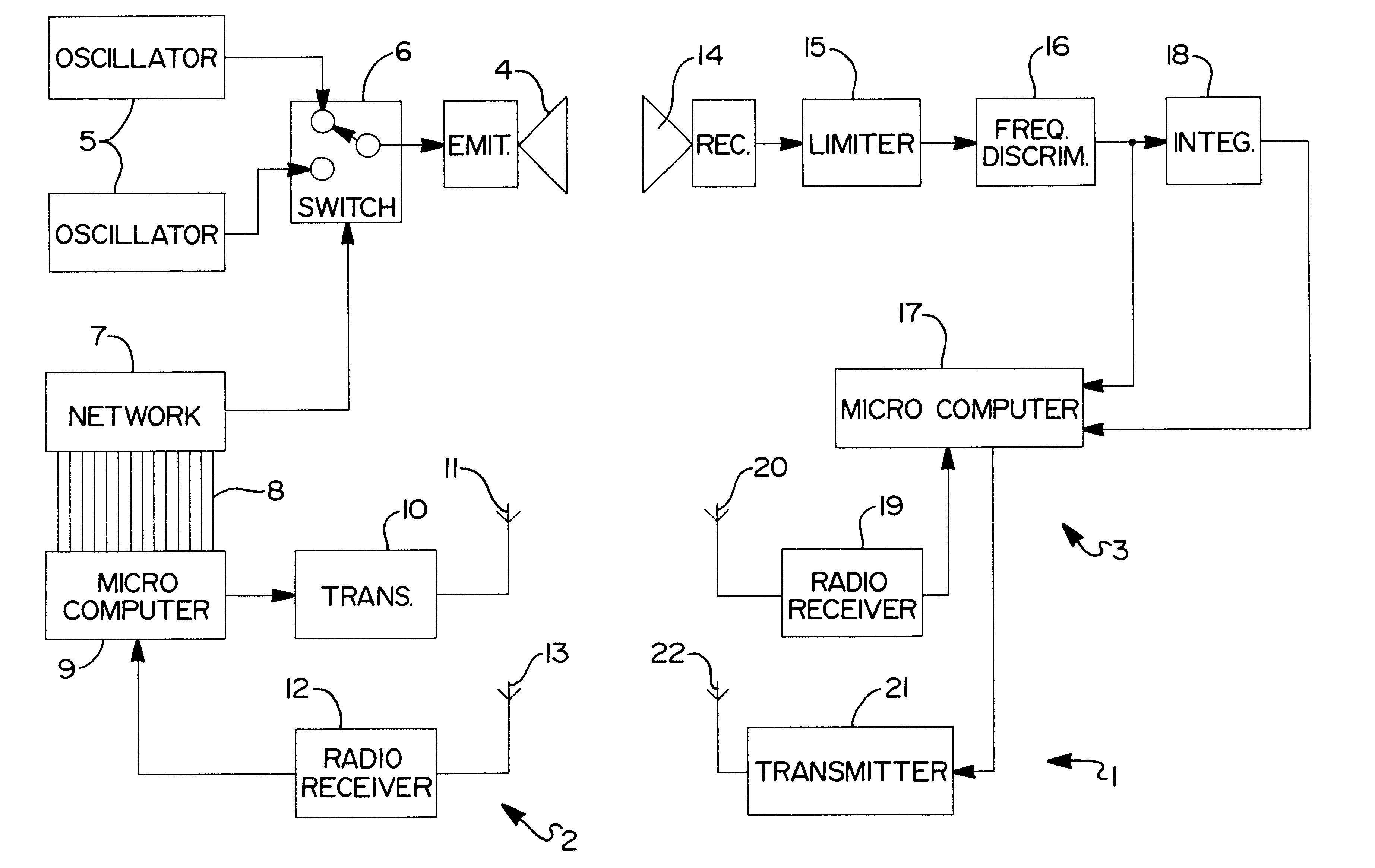
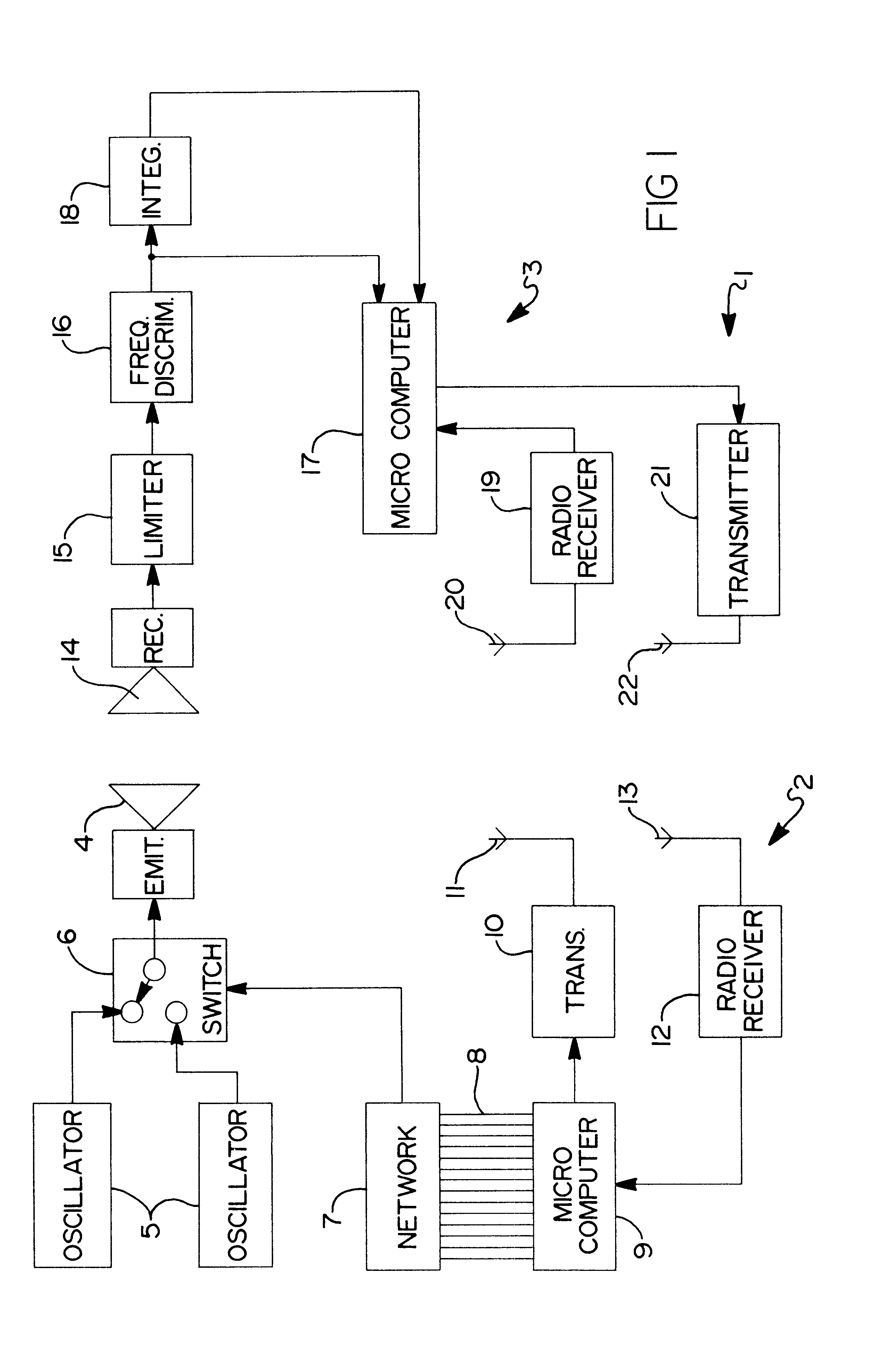
Referring to FIG. 1, there is shown a distance measuring system 1 to aid the visually impaired. The distance measuring system 1 comprises one or more transmitters 2 (of which only one is shown in FIG. 1) and one or more receivers 3 (of which only one is also shown), the transmitters 2 being arranged at fixed locations and each receiver 3 being carried by a visually impaired person.

The transmitter comprises an ultra-sonic emitter 4 connected to a pair of oscillators 5 for generating signals at frequencies of 39.6 and 40.4 kilohertz respectively, via respective outputs of a digital switch 6. The frequencies of the oscillators S are sufficiently close together that a narrow band width transmitter can be used.

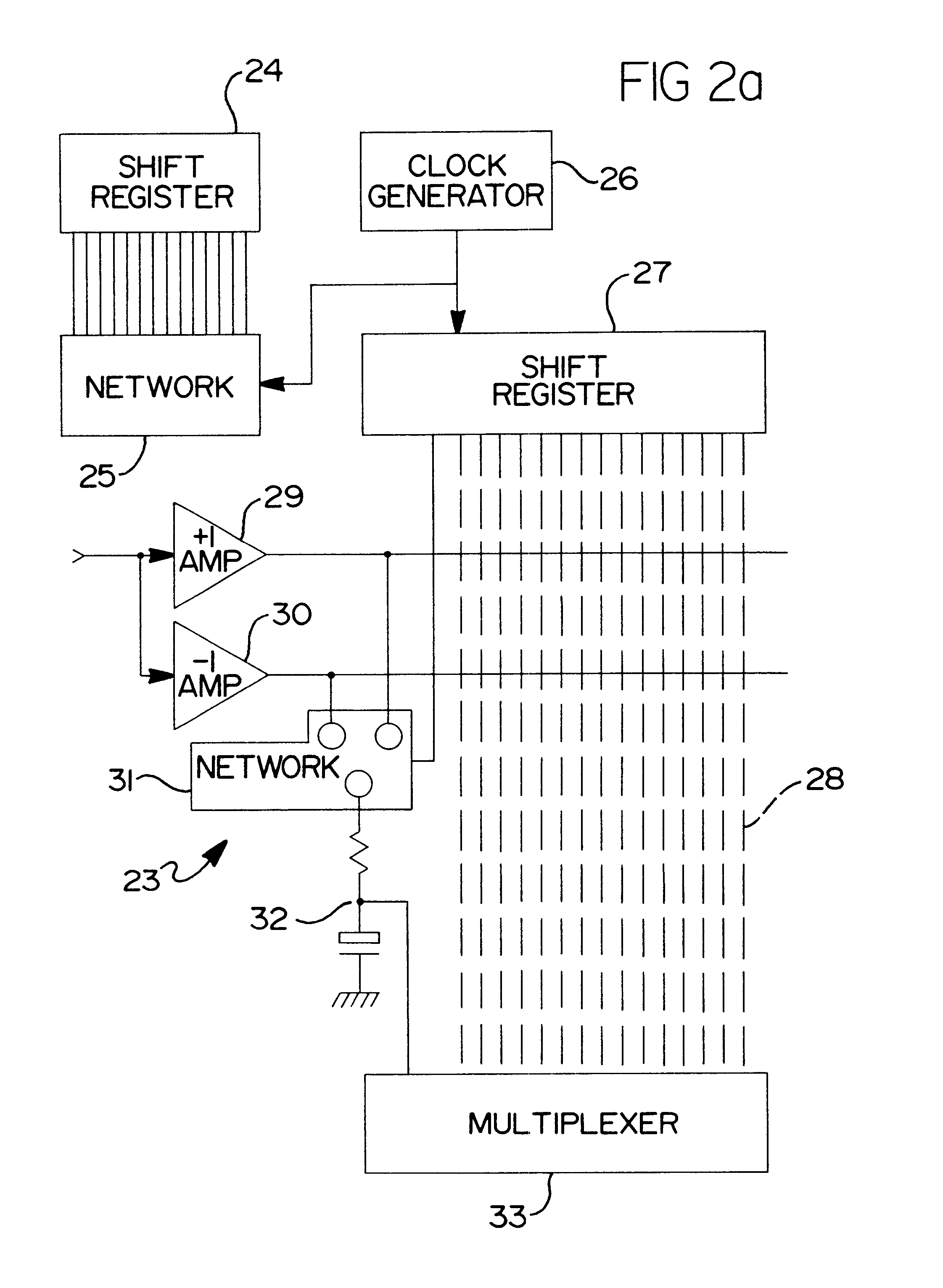
By using ultra-sonic frequencies of 39.6 kHz and 40.4 kHz, if the chip width is 2.5 ms, then there are exactly 101 cycles at 40.4 kHz and 99 cycles of 39.6 kHz in one chip. This enables the two frequencies to be made to have the same leading edge where the new chip of the sequence...


PUM


Abstract

A method and apparatus for distance measurement is disclosed in which first and second signals having different propagation speeds are transmitted between a transmitter (2) at a first location and a receiver (3) at a second location. The distance between the first and second locations is determined from the difference in propagation time between the first and second signals.

Description

1. Field of the InventionThe present invention relates to a method and apparatus for distance measurement.2. Description of the Related ArtDistance measurement techniques exist in which acoustic signals in the ultra-sonic range are transmitted in the form of short pulses by a narrow band transmitter and are detected by a sensor. In such devices, the interval between pulses must be longer than the time taken for the ultra-sonic signal to travel between the transmitter and the detector in order to avoid ambiguity in pulses detected at the sensor. This in turn limits the distance over which the device can be used or the speed of response.Preferred embodiments of the present invention seek to overcome the above drawback of the prior art.According to an aspect of the present invention, there is provided a distance measuring method comprising the steps of transmitting between at least one pair of first and second locations a respective ultrasonic signal, transmitting between the or each p...

Claims


Application Information

Patent Timeline
IPC IPC(8): G01S1/74G01S11/00G01S11/16G01S1/00
CPCG01S11/16G01S1/74G01S1/75
Inventor BURRELL, CHRISTOPHER SIMON
Owner GUIDE DOGS FOR THE BLIND ASSOC THE
Learn More