Apparatus and method using an array of ultrasonic sensors for determining the velocity of a fluid within a pipe

a technology of ultrasonic sensors and fluids, applied in liquid/fluent solid measurement, instruments, machines/engines, etc., can solve the problems of slow update rate and relatively inaccurate, slow and inaccurate, and the reliability and accuracy problems of clamp-on ttufs, etc., to achieve the effect of robust flow meter

Active Publication Date: 2008-06-17
EXPRO METERS
View PDF133 Cites 63 Cited by
  • Summary
  • Abstract
  • Description
  • Claims
  • Application Information

AI Technical Summary

Benefits of technology

[0016]Objects of the present invention include providing an apparatus having an array of ultrasonic sensor units for measuring the velocity of a fluid flowing within a pipe wherein beam forming techniques are used to provide a robust flow meter.

Problems solved by technology

Although CCFU's are operationally more robust than other ultrasonic interpretation techniques, they suffer from drawbacks attributed to most cross correlation flow meters, i.e., they are have slow update rates and relatively inaccurate.
While this requirement does not pose a significant issue for in-line, wetted transducer TTUFs, it does pose a challenge for clamp-on devices by introducing the ratio of sound speed in the pipe to the fluid as an important operating parameter.
The influence of this parameter leads to reliability and accuracy problems with clamp-on TTUFs.
The primary issue with CCFUs is that they are slow and inaccurate.

Method used


Image

  • Apparatus and method using an array of ultrasonic sensors for determining the velocity of a fluid within a pipe
  • Apparatus and method using an array of ultrasonic sensors for determining the velocity of a fluid within a pipe
  • Apparatus and method using an array of ultrasonic sensors for determining the velocity of a fluid within a pipe

Examples


Embodiment Construction

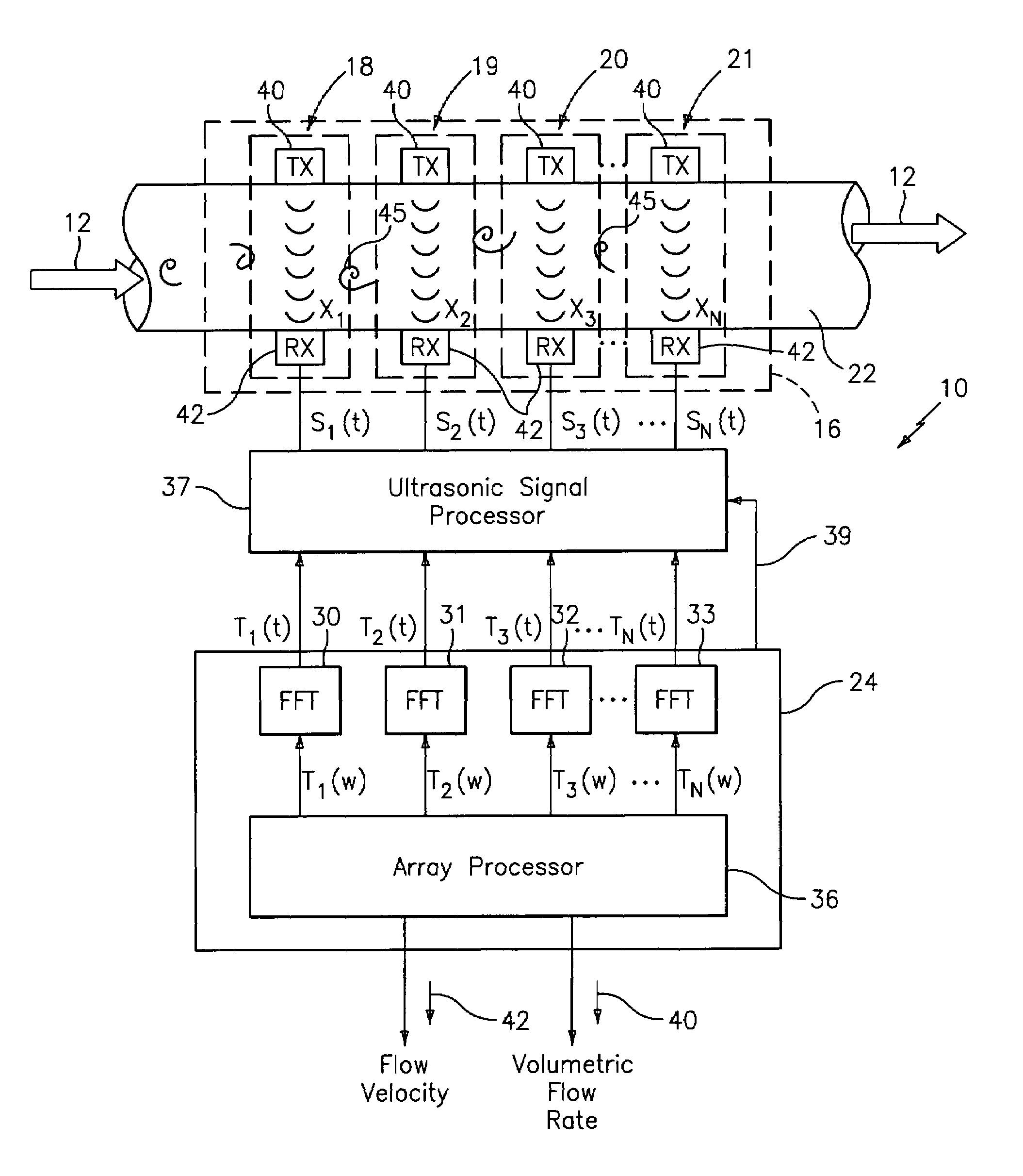
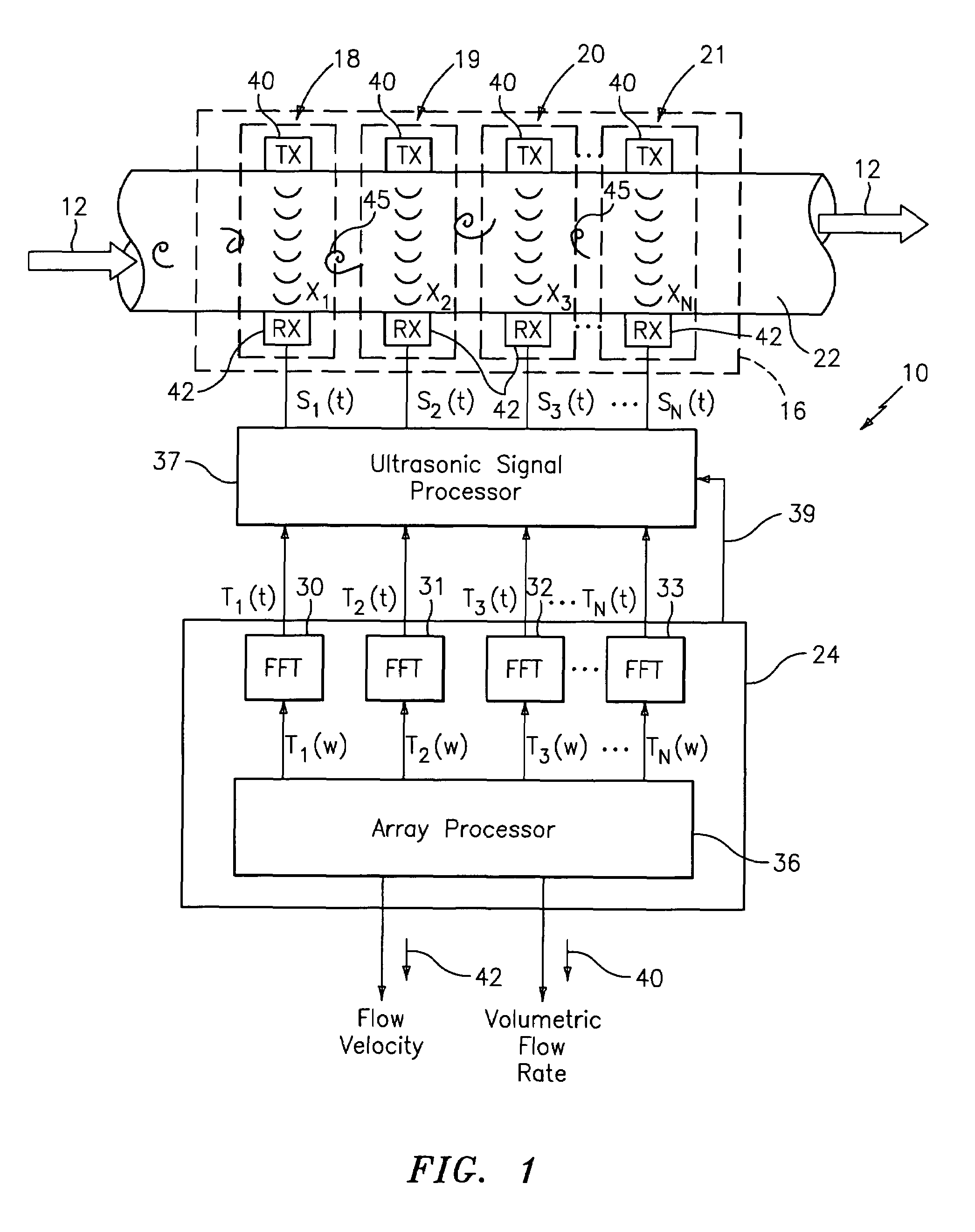
[0041]Referring to FIG. 1, a flow meter, generally shown as 10, is provided to measure the velocity and / or volumetric flow rate of a single phase fluid 12 (e.g., gas, liquid or liquid / liquid mixture) and / or a multi-phase mixture 12 (e.g., process flow) flowing through a pipe. The multi-phase mixture may be a two-phase liquid / gas mixture, a solid / gas mixture or a solid / liquid mixture, gas entrained liquid or a three-phase mixture.

[0042]The flow meter 10 includes a sensing device 16 comprising an array of ultrasonic sensor units 18-21. Each sensor unit comprises a pair of ultrasonic sensors 40,42, one of which functions as a transmitter (Tx) 40 and the other as a receiver (Rx) 42. The sensor units 18-21 are spaced axially along the outer surface 22 of a pipe 14 having a process flow 12 propagating therein. The pair of sensors 40,42 is diametrically disposed on the pipe at predetermined locations along the pipe to provide a through transmission configuration, such that the sensors tran...


PUM

PropertyMeasurementUnit
transmission frequencyaaaaaaaaaa
frequencyaaaaaaaaaa
frequencyaaaaaaaaaa

Abstract

An apparatus and method for measuring the flow velocity of a fluid flowing through a pipe that includes an array of at least two ultrasonic sensor units (with as many as 16 sensor units) disposed at predetermined locations along the pipe. Each sensor unit includes an ultrasonic transmitter and an ultrasonic receiver. Each sensor unit provides a respective signal indicative of a parameter of the transit time or amplitude of the ultrasonic signal propagating between each respective ultrasonic transmitter and ultrasonic receiver. A signal processor defines a convective ridge in the k-ω plane in response to the ultrasonic signals using an adaptive beamforming algorithm, such as Capon and Music. The signal processor further determines the slope of at least a portion of the convective ridge to determine the flow velocity of the fluid.

Description

CROSS-REFERENCE TO RELATED PATENT APPLICATIONS[0001]The present application claims the benefit of U.S. Provisional Patent Application, Ser. No. 60 / 439,715 filed Jan. 13, 2003, U.S. Provisional Patent Application, Ser. No. 60 / 524,066 filed Nov. 21, 2003, U.S. Provisional Patent Application, Ser. No. 60 / 531,065 filed Dec. 19, 2003, U.S. Provisional Patent Application, Ser. No. 60 / 447,498 filed Feb. 14, 2003, and U.S. Provisional Patent Application, Ser. No. 60 / 440,014 filed Jan. 14, 2003, which are all incorporated herein by reference.FIELD OF THE INVENTION[0002]The present invention pertains to the field of processing ultrasonic signals such as in the field of sonar, and more particularly to the field of measurements of the velocity of a fluid when the direction of fluid flow is known, such as when the fluid flow is confined to a pipe.BACKGROUND OF THE INVENTION[0003]Currently, there are three classes of flow meters that utilize ultrasonic transducers, which include transit time ultr...

Claims


Application Information

Patent Timeline
Patent Type & Authority Patents(United States)
IPC IPC(8): G01F23/00G01F1/7082G01F1/712G01F1/74G01N29/024G01N29/032G01N29/22G01N29/34G01P5/24
CPCG01F1/662G01F1/666G01F1/667G01F1/7082G01F1/712G01F1/74G01N29/024G01N29/032G01N29/222G01N29/348G01P5/245G01N2291/011G01N2291/02408G01N2291/02416G01N2291/02425G01N2291/02836G01N2291/102G01N2291/106
Inventor KERSEY, ALAN D.GYSLING, DANIEL L.
Owner EXPRO METERS
Why Eureka
Try Eureka