Localization system, robot, localization method, and sound source localization program

a technology of localization system and sound source, applied in the field of localization system, can solve the problem that the robot cannot operate the actuator to grab the object, and achieve the effect of measuring accurately

Inactive Publication Date: 2009-10-22
NEC CORP
View PDF0 Cites 65 Cited by
  • Summary
  • Abstract
  • Description
  • Claims
  • Application Information

AI Technical Summary

Benefits of technology

[0017]As the present invention is configured and works as described above, the object detection unit effectively works to recognize the arranging state of surrounding objects present around a plurality of microphones, and while considering reflection of an ultrasonic wave generated depending on the arranging state of the objects, candidate areas where the ultrasonic tag may be present are calculated from the positions of the microphones in the microphone array, and an area where the candidate areas where the ultrasonic tag may be present calculated from the respective microphones are overlapped is determined as the position of the ultrasonic tag. As such, compared from the case where reflection by the surrounding objects is not considered, the three-dimensional position of the sound source such as an ultrasonic tag can be calculated accurately for example, and even in a room where reflection of an ultrasonic wave by objects is frequently caused, measurement of the position of the sound source, that is, the positional relationship between the ultrasonic tag and the microphones can be measured accurately, for example. As such, it is possible to provide an excellent localization system which has not been able to be achieved conventionally, and a robot and a localization method using the localization system, and its sound source localization program.

Problems solved by technology

For example, when the user instructs the robot to bring an object, the robot cannot operate the actuator to grab the object unless the robot detects the position of the instructed object.

Method used


Image

  • Localization system, robot, localization method, and sound source localization program
  • Localization system, robot, localization method, and sound source localization program
  • Localization system, robot, localization method, and sound source localization program

Examples


first exemplary embodiment

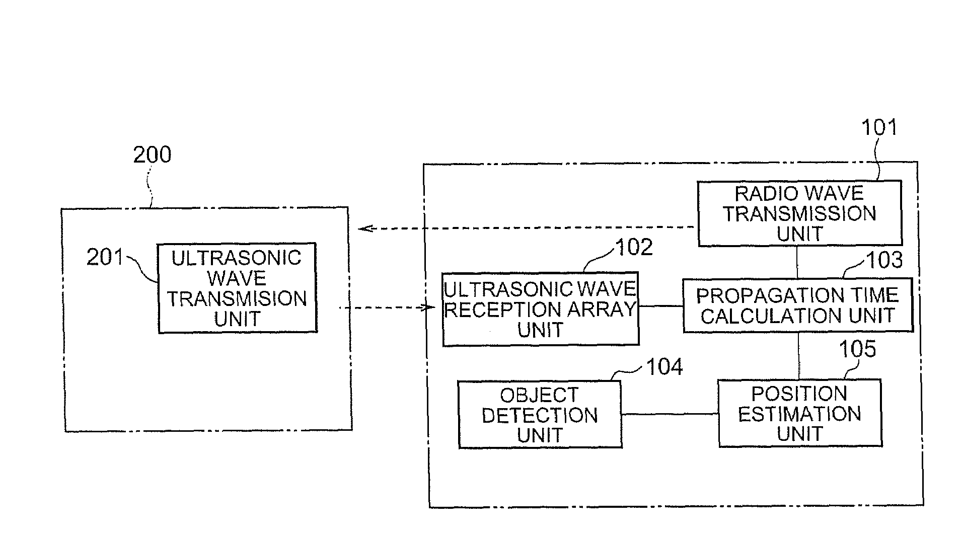
[0019]A first exemplary embodiment will be described based on FIGS. 1 to 8.

[0020]First, the overview of the exemplary embodiment and the principle contents of the exemplary embodiment will be described, and then a specific exemplary embodiment of the invention will be described.

[0021]First, a localization system of the exemplary embodiment acquires the positions and the shapes of objects present around a microphone array and an ultrasonic tag by an object detection unit. Thereby, the system is capable of calculating the shortest paths from the ultrasonic wave transmission unit provided to the ultrasonic tag to the respective microphones configuring the microphone array, while considering reflection of the sound wave on the objects. With this configuration, with the elapsed time from the time that the sound wave is emitted from the ultrasonic wave transmission unit of the ultrasonic tag until it reaches the respective microphones being observed, it is possible to accurately calculate...

second exemplary embodiment

[0080]Next, a second exemplary embodiment will be described based on FIG. 9.

[0081]The second exemplary embodiment shown in FIG. 9 differs from the first exemplary embodiment in that the object detection unit 104 includes an object detection sensor and a sensor moving mechanism 106 for moving the object detection sensor.

[0082]As shown in FIG. 9, the localization system of the second exemplary embodiment adopts a method in which the sensor moving mechanism 106 of the object detection unit 104 detects various kinds of information regarding surrounding objects in a plurality of locations, the object detection unit 104 processes them and creates an object map, and performs localization using the created object map. By considering movement of the objects, it is possible to generate an object map of a wider area than that the object detection unit 104 can sense at once. Note that an exemplary embodiment of the sensor moving mechanism 106 may be a configuration in which the whole or a part ...

third exemplary embodiment

[0097]Next, a third exemplary embodiment will be described based on FIG. 11.

[0098]The localization system according to the third exemplary embodiment disclosed in FIG. 11 is characterized as to include, in addition to the configuration of the first exemplary embodiment shown in FIG. 1, a surrounding object identifying function for previously detecting what the surrounding objects K11 and S11 are, and an object matching unit 107 which stores the detection result in the memory and transmits the shape of a stored surrounding object to the object detection unit 104 corresponding to a request from the outside.

[0099]Further, the object detection unit 104 has a function of creating an object map for identifying objects in an area which is outside the sensor measuring range by using the object shape information provided from the object matching unit 107.

[0100]Here, the object matching unit 107 includes an object identifying unit 107A for identifying objects and an object shape storing unit ...


PUM


Abstract

To measure an accurate positional relationship between an ultrasonic tag and a microphone and identify a sound source position, even if an object is present between the ultrasonic tag and the microphone. When a radio transmission unit transmits a radio wave, an ultrasonic wave transmission unit of an ultrasonic tag receives it and transmits an ultrasonic wave. Then, a plurality of microphones in an ultrasonic wave reception array unit receive the ultrasonic wave. A propagation time calculation unit calculates a time from when the radio wave is transmitted by the radio transmission unit till when an ultrasonic wave reaches each of the microphones in the ultrasonic wave reception array unit. A position estimation unit calculates the position (sound source) of the ultrasonic tag according to the arrival time at each of the microphones and the result of object detection while considering reflection of the ultrasonic wave.

Description

TECHNICAL FIELD[0001]The present invention relates to a localization system for measuring the position of an object which generates sound waves. In particular, the present invention relates to a localization system for measuring the position of an object when an sound wave reflecting object is present near the object, a robot and a localization method utilizing this localization system, and its sound source localization program.BACKGROUND ART[0002]Knowing positions (one-dimensional position, two-dimensional position, and three-dimensional position) of objects and human beings is an important technique in human interfaces and robots. For instance, regarding a robot which performs voice interaction with a human being, it is expected that the voice recognition performance will be improved by directing the microphone orientation to a user with whom the robot will have a dialogue, and it is also expected that causing the face of the robot to face the user when they have a dialogue will p...

Claims


Application Information

Patent Timeline
Patent Type & Authority Applications(United States)
IPC IPC(8): G01S3/80
CPCG01S5/30G01S17/08G01S11/16
Inventor FUNADA, JUNICHI
Owner NEC CORP
Why Eureka
Try Eureka