This parallel setting sets limitations on the region of possible movement of the artificial knee joint.
In particular, it is difficult to achieve maximum flexion.
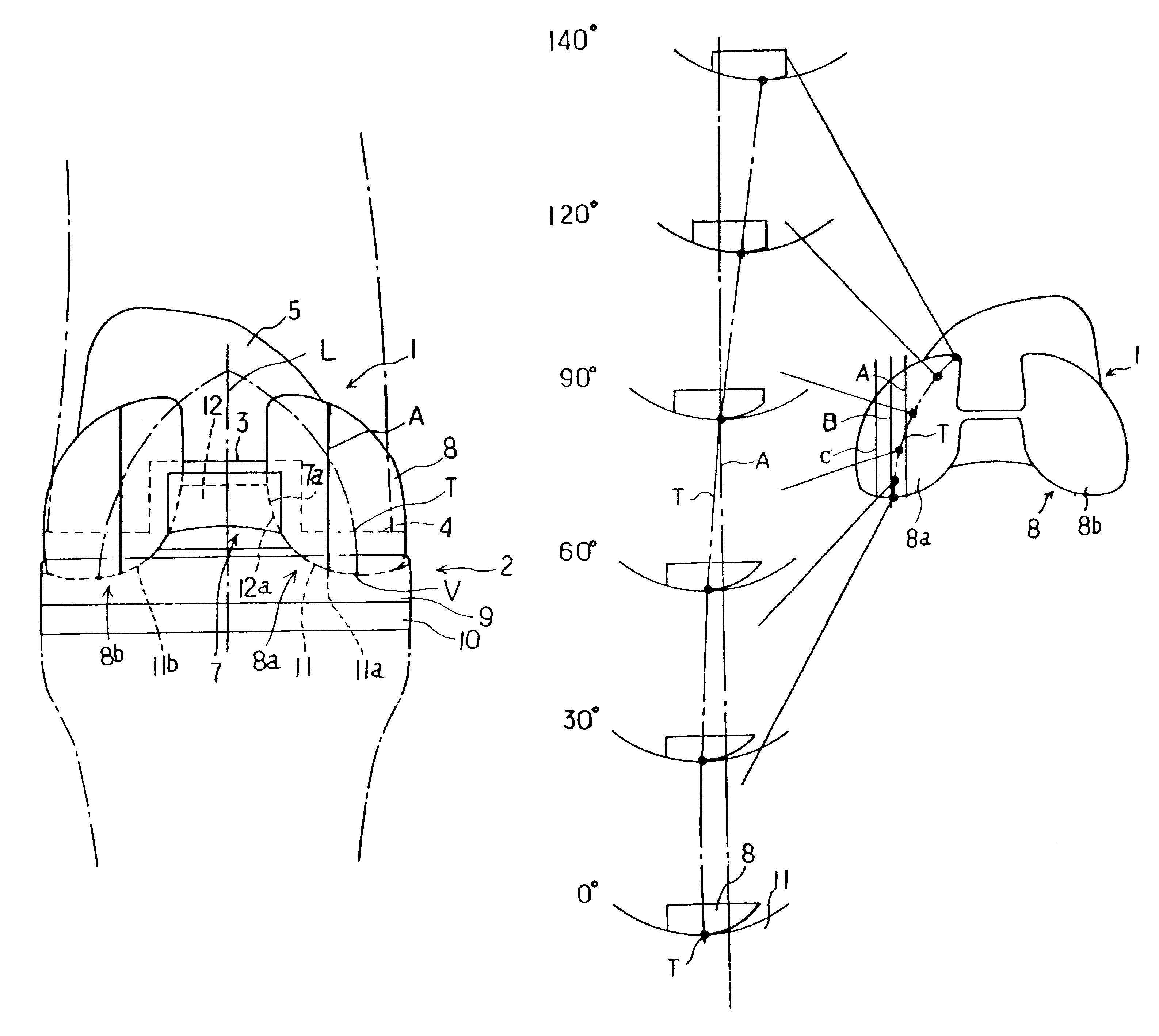
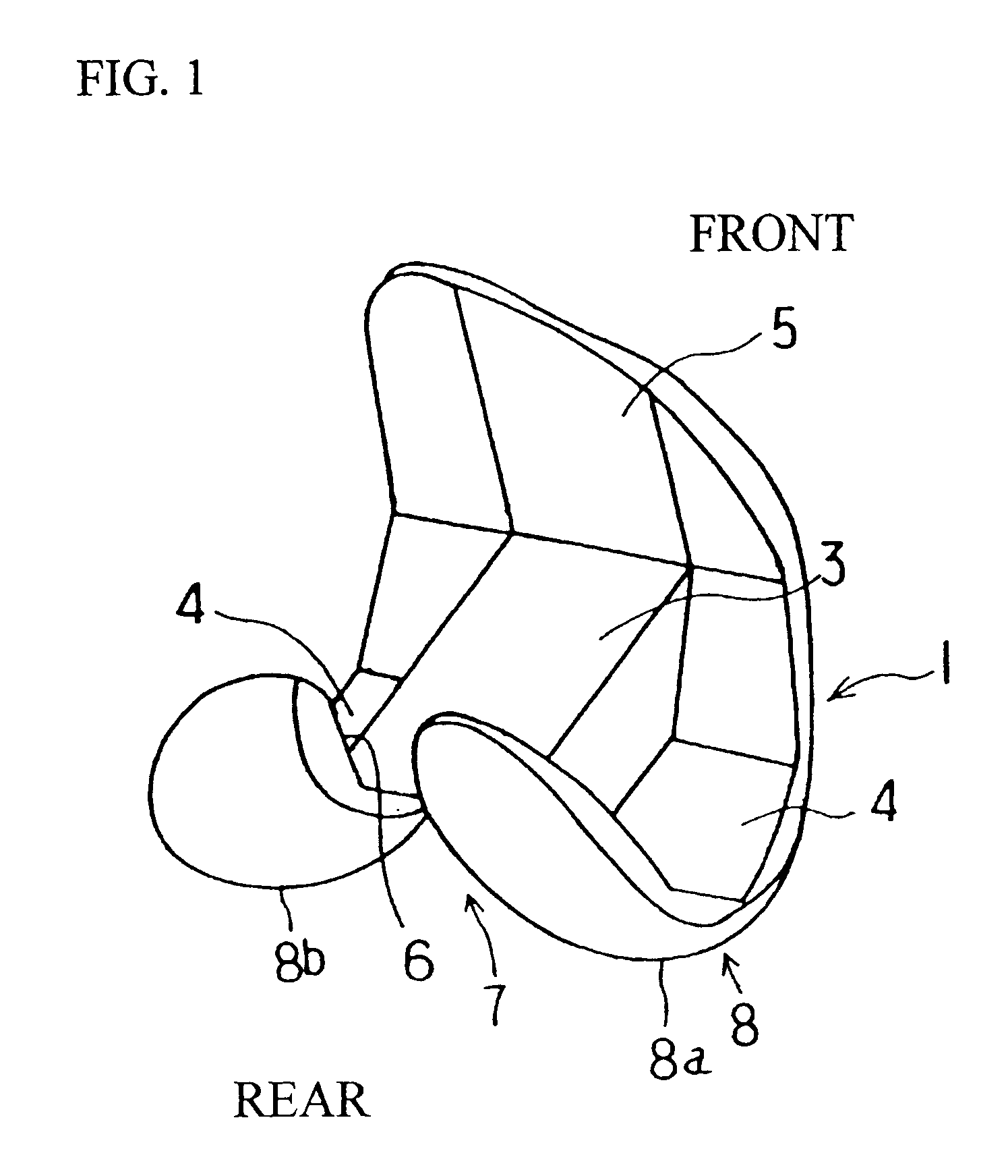
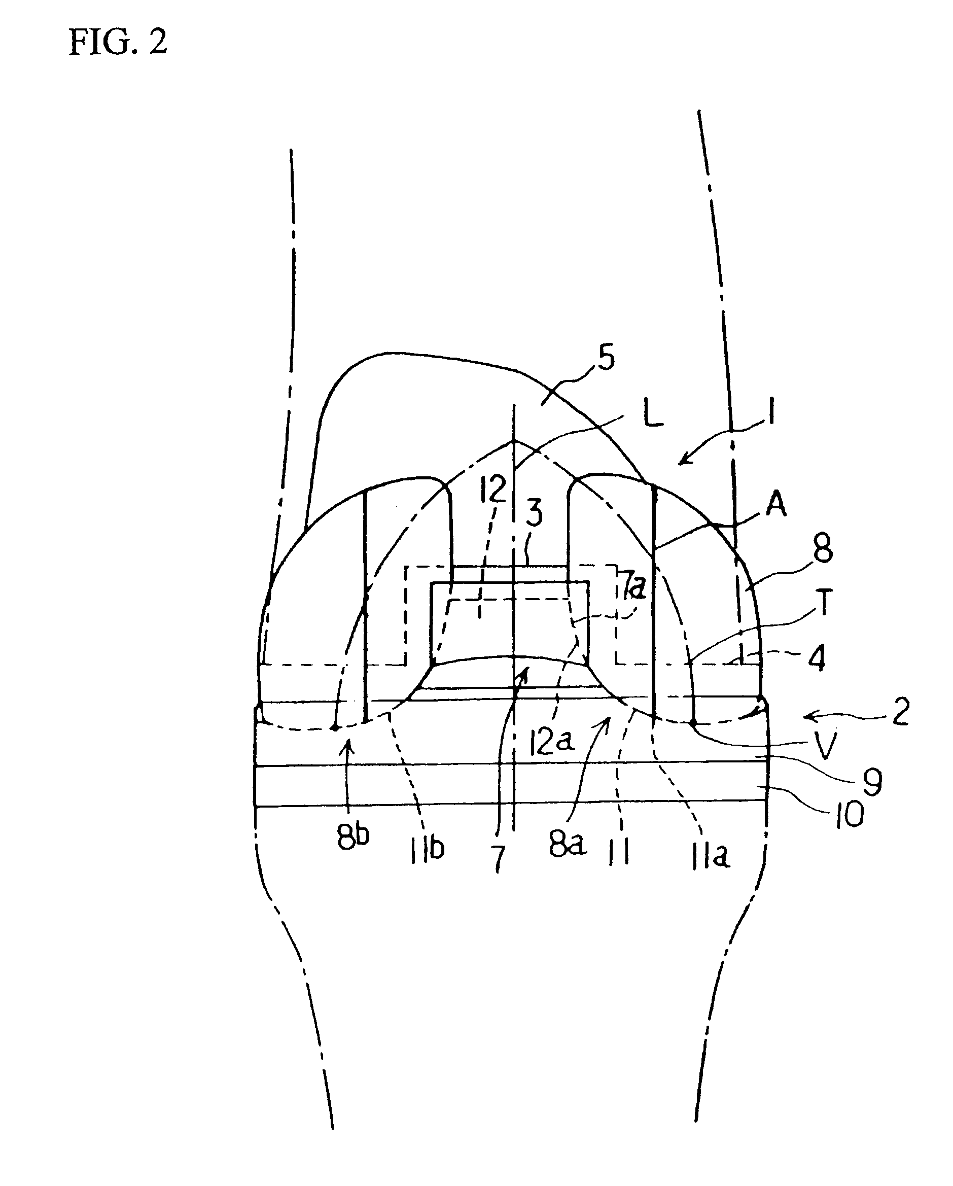
1. The tibial condylar portion that supports the femoral condylar portion forms an elliptical groove that has its
long axis in the anteroposterior direction as seen in a plan view. The femoral condylar portion rotates while sliding and rolling through this elliptical groove, thus allowing flexion of the knee. In this case, the femoral condylar portion is contained within the vertically projected plane of the tibial condylar portion, and does not protrude from this plane in extension. However, since the center of rotation of the femoral condylar portion moves to the rear as the angle of flexion increases, the femoral condylar portion protrudes from the vertically projected plane of the elliptical surface of the tibial condylar portion. Since the edge of the femoral condylar portion, and especially the posterior portion, contacts the running part of the
hamstring on both the medial and lateral, this protrusion of the femoral condylar portion interferes with the normal tension of the
hamstring, and therefore impedes flexion.
2. In a biological knee joint, the tibial condylar portion is more or less planar in the anteroposterior direction, and the attitude of the
femur during flexion is controlled by the anterior and posterior cruciate ligaments. More specifically, the posterior cruciate ligaments gradually extend up to a
flexion angle of approximately 60.degree., and then remain more or less fixed, so that the attitude is controlled. In an artificial knee joint, on the other hand, the side-
surface shape of the tibial condylar portion is formed with the standing position of 0.degree. as the deepest point, and with recessed shapes showing the shape of a "ship
hull" before and after this deepest point, so that smooth rotation of the femoral condylar portion is achieved. In this case as well, a semi-constrained type configuration in which the curvature
radius of the recessed shapes of the tibial condylar portion is greater than the curvature
radius of the protruding shapes of the femoral condylar portion is most common. Consequently, as the femoral condylar portion bends, the position of the contact surface with the tibial condylar portion gradually becomes higher, which differs from the movement of a biological knee joint. Accordingly, when the cruciate ligaments are retained, the extension of these ligaments becomes excessive, so that
attitude control becomes difficult to achieve. Even in cases where the cruciate ligaments are excised, the extension of the medial and lateral collateral ligaments is excessive, and smooth flexion is impeded.
3. In order for the femoral condylar portion to obtain a large
flexion angle, the condylar portion must be correspondingly extended upward and to posterior. However, in the case of parallel setting that requires a
wide area, this interferes with ligaments and tendons that are present in the upper posterior area, so that this extension cannot be made very long. As a result, the
flexion angle in a conventional artificial knee joint is limited to approximately 110 to 120.degree.. However, flexion of approximately 150.degree. is necessary for, for instance, an upright sitting on a plane surface or a Japanese-style sitting position, etc.
4. In a biological knee joint, the smoothness of flexion is aided by an internal and external
axial rotation movement of the
femur as the flexion angle increases. However, if the femoral condylar portion and tibial condylar portion are set parallel to each other, this internal and external
axial rotation movement is restricted. In other words, when the flexion angle increases, the femoral condylar portion leaves the recessed groove of the tibial condylar portion and is lifted upward, so that normal
axial rotation is hindered, and the cruciate ligaments and medial and lateral collateral ligaments are excessively extended. Thus, smooth flexion and axial rotation are difficult.

