Composite sealant and splice case therefor

a sealing case and splice technology, applied in the field of electric cables, can solve the problems of not being able to easily remove all of the mastic from the flange, using this mastic, and adding to the cost of repairing the conductor, etc., and achieve the effect of convenient assembly of the splice case and easy inventoried and stored for us

Inactive Publication Date: 2002-06-18
UNISEAL
View PDF9 Cites 79 Cited by
  • Summary
  • Abstract
  • Description
  • Claims
  • Application Information

AI Technical Summary

Benefits of technology

The objective of this invention is to provide a mastic or a composite sealant which attaches itself to the closure of the flanges 16 during installation so that the sealant will not fall away from the closure or splice case thereby making it easier to assemble the splice case;
A further object is to provide such a mastic which acts as a sealant between the two half members of the splice case and yet which mastic allows the splice case to be readily opened to make adjustments in regard to the electrical conductors inside of the splice case.
In other words, the mastic or sealant must have sufficient adhesive properties to adhere to the closure when the two half-members of the closure are

Problems solved by technology

There is a disadvantage with the use of this mastic.
The disadvantage is that if it be necessary to open the tubular member 10, it is difficult because of the adhesive property or the stickiness of the mastic.
The removal of the mastic from the flanges 16 is time consuming and difficult which adds to the expense of repairing the conductors 50 and 52.
Often, all of the mastic cannot readily be removed from the flanges.
A problem exists in regard to the quality control of the R Sealing Tape in

Method used


Image

  • Composite sealant and splice case therefor
  • Composite sealant and splice case therefor
  • Composite sealant and splice case therefor

Examples


Embodiment Construction

)

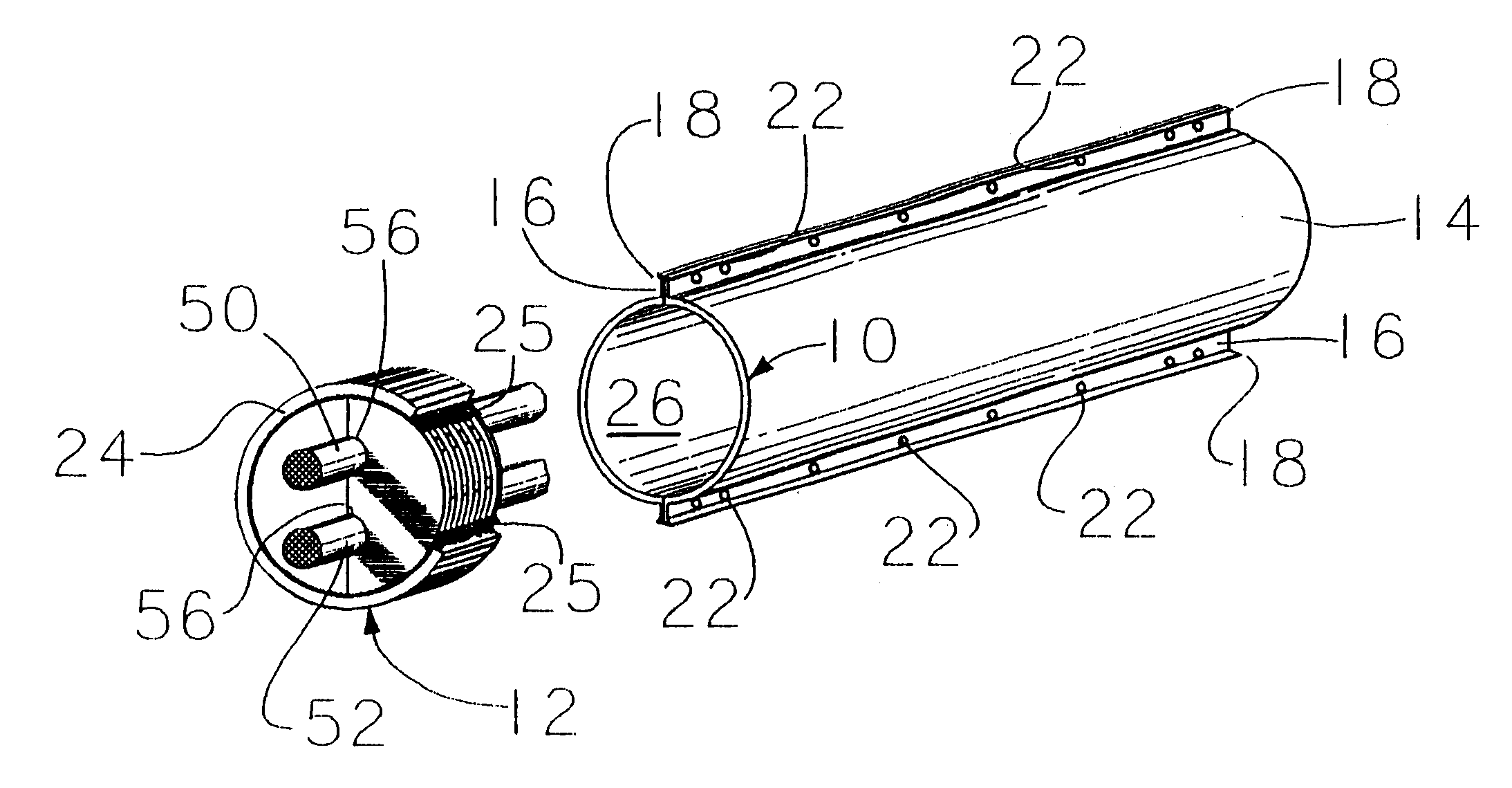
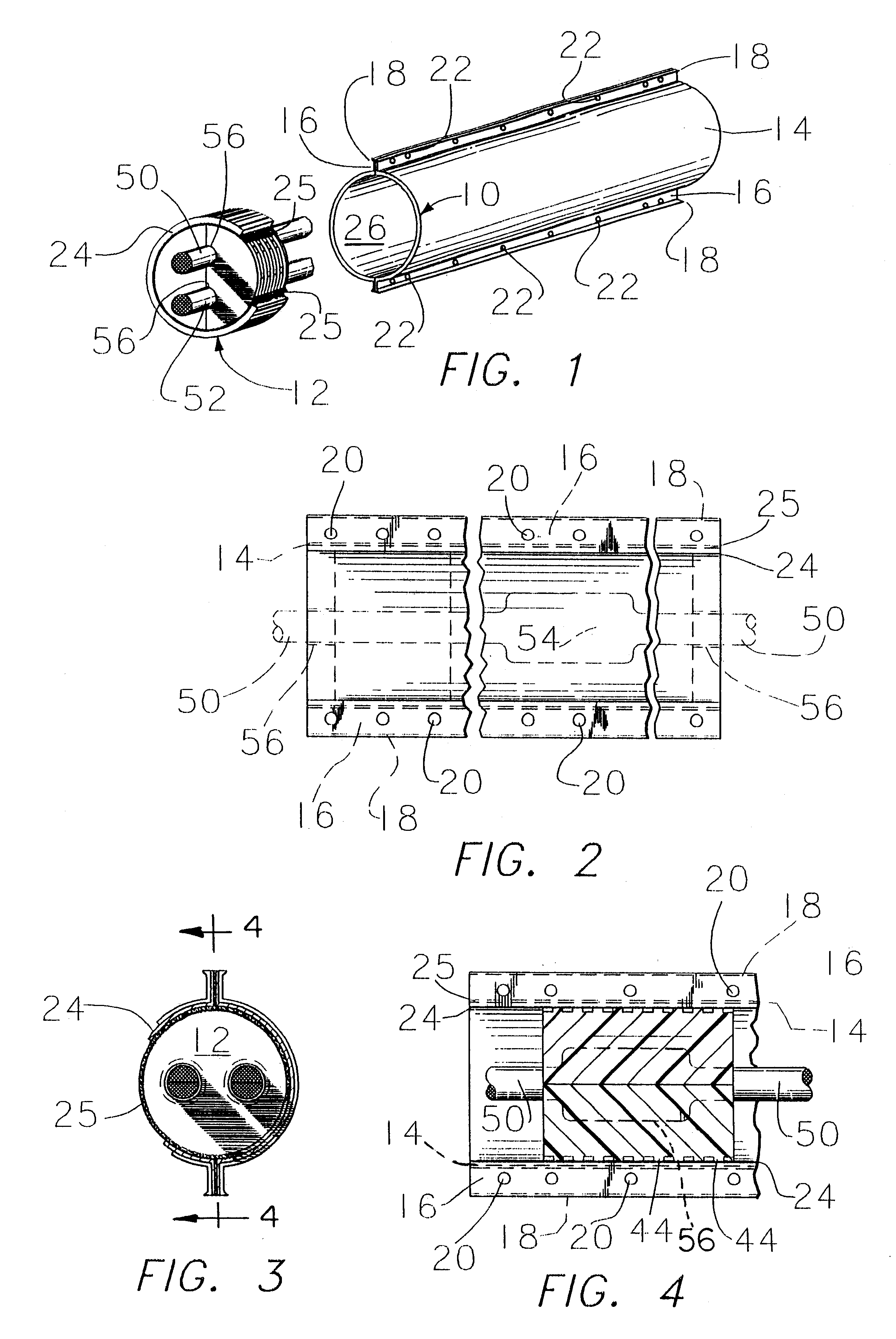
In the drawings it is seen that the splice case comprises a tubular member 10 and two end seals 12.

The tubular member 10 actually is composed of two half tubular members 14 having in a lateral cross-sectional view a configuration of a semi-circular member. On the free ends of the semi-circular member 14 there is a flange 16 which bends back on the member 14 to form a lip 18. On each member 14 there are two flanges 16.

In the flanges 16 there are holes 20. To assemble the two half tubular members 14 into the tubular member 10 a number of nut and bolt combinations 22 are positioned in the openings 20 of two adjacent flanges 16. As is seen, in FIGS. 1 and 3, there results the tubular member 10.

There is a composite 23 comprising a sealant 24 and an adhesive 25. A separator 27 may be placed over the adhesive 25 and peeled away when the composite 23 is being applied.

In FIGS. 2, 3, and 4 the composite 23 is attached to the flanges 16 by means of adhesive 25.

FIGS. 12, 13, and 14 illustrate ...


PUM


Abstract

A protective splice case for communication cables includes two half tubular members and two cylindrical end seals. A composite material, in the form of a non-tacky, resilient and yieldable sealant non-releasably secured to an adhesive, is positioned between the two half members, with the adhesive contacting one of the two half members and the non-tacky sealant facing the other of the two half members. Also, the composite is positioned between the end seals and the half members, with the adhesive contacting the outer surfaces of the end seals and the non-tacky sealant facing the interior surfaces of the two half members. The result is a splice case which keeps the extraneous material such as water, dust, dirt and snow from reaching the interior of the splice case, and is yet reusable and reenterable for repairs and inspection.

Description

(C) STATEMENT AS TO RIGHTS TO INVENTIONS MADE UNDER FEDERALLY SPONSORED RESEARCH AND DEVELOPMENTThe applicant used his own resources in developing this invention and there was no assistance from the United States Government.(d) BACKGROUND OF THE INVENTION1. Field of the InventionElectrical cables, especially communication cables, comprise a number of individual conducting members. These conducting members may be wires such as copper wire or may be a fiberoptic. The members are individual conductors of information.Unfortunately, the communication cable may be damaged or cut or broken or even severed. With damage to the cable, it is necessary to splice together the individual conductors of information.The communication cable as manufactured has a protective outer sheath of material. With damage to the communication cable, this outer protective sheath is broken and it is possible for extraneous material such as water, snow, dust and dirt to work into the interior of the communication c...

Claims


Application Information

Patent Timeline
IPC IPC(8): H02G15/00H02G15/10H02G15/113H02G15/013
CPCH02G15/113H02G15/013
Inventor SMITH, DONALD J.
Owner UNISEAL
Why Eureka
Try Eureka