Control valve

a control valve and valve body technology, applied in the direction of valve housings, fluid couplings, servomotors, etc., can solve the problems of increasing assembly manpower, deteriorating working environment of operators, pressure fluid hoses still interfering with operator's stepping up or down,

Inactive Publication Date: 2002-06-25
NIHON KENKI CO LTD
View PDF10 Cites 36 Cited by
  • Summary
  • Abstract
  • Description
  • Claims
  • Application Information

AI Technical Summary

Problems solved by technology

Due to the above-mentioned tendency of arrangement of more pressure fluid hoses, however, such pressure fluid hoses still interfere with operator's stepping up or down even when the foot area has become wider.
It has also been pointed out that due to heat from these pressure fluid hoses, the operator's seat tends to become hot

Method used


Image

  • Control valve
  • Control valve
  • Control valve

Examples


Embodiment Construction

The embodiment of the control valve according to the present invention will hereinafter be described based on the drawings.

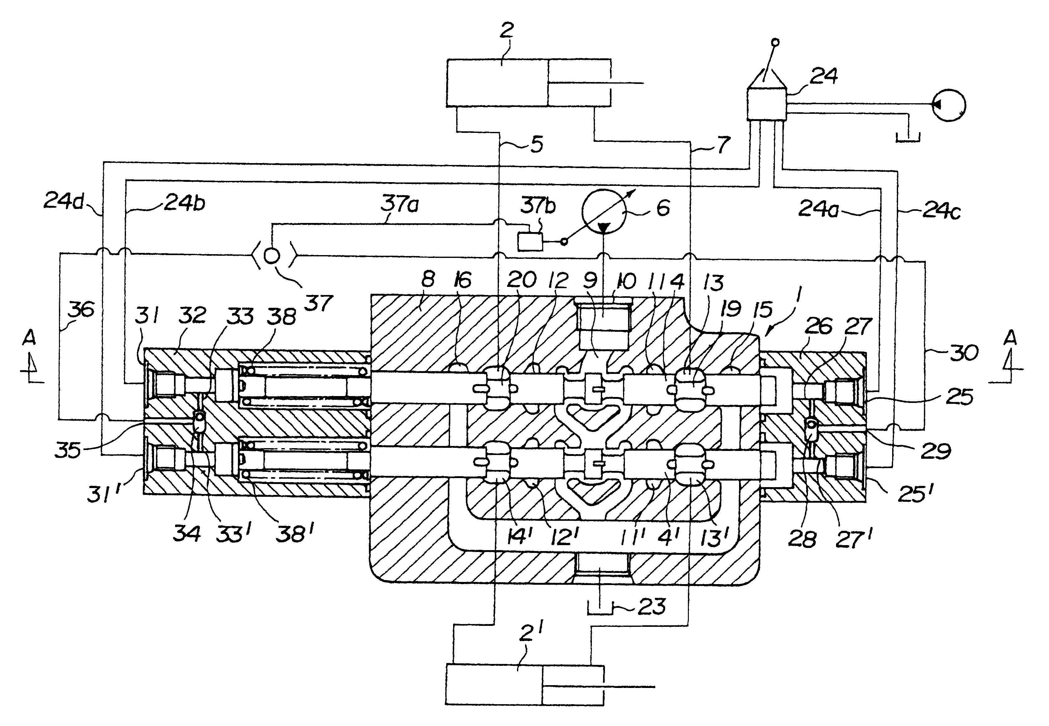
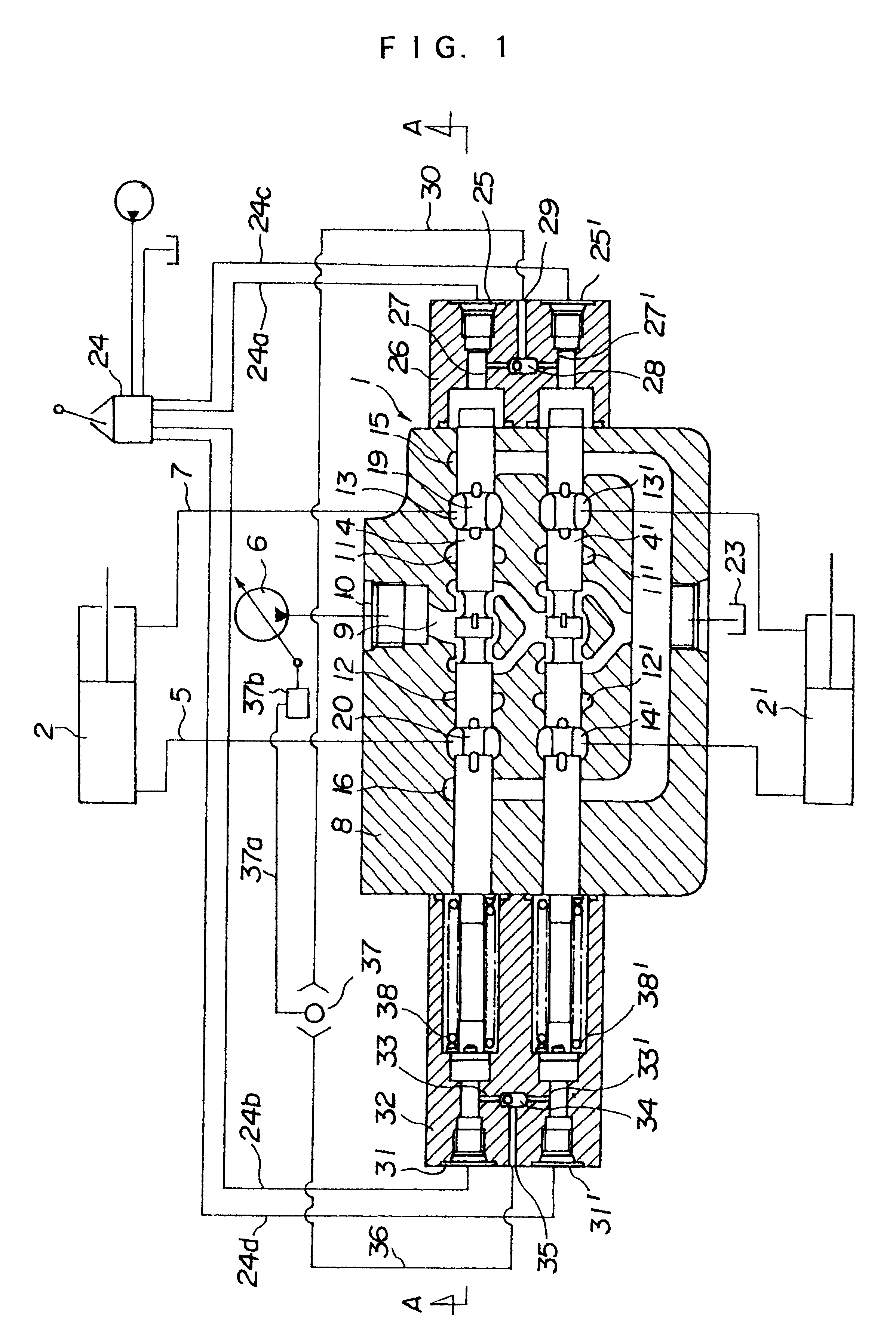
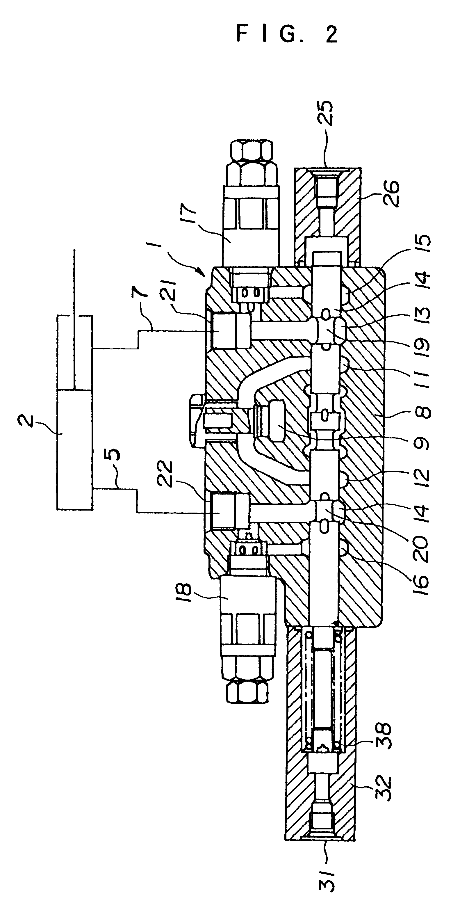
FIG. 1 and FIG. 2 show the control valve 1 according to the present invention, actuators, for example, hydraulic cylinders 2,2' to be changed over under control by the control valve 1, and a hydraulic remote control valve 24 for changing over under control the control valve 1. The hydraulic remote control valve 24 is provided with four hydraulic pilot valves in this embodiment as in the conventional remote control valve 70 depicted in FIG. 3.

Inside a valve body 8 of the control valve 1 according to this embodiment, plural, for example, two internal bores are formed. Spools 4,4' are movably arranged within the respective internal bores. Movements of the respective spools 4,4' are effected by pilot pressures which are transmitted through pilot lines 24a,24b,24c,24d which connect the hydraulic remote control valve 24 and the control valve 1 with each other. These p...


PUM


Abstract

It is an object of the present invention to provide a control valve which can reduce the number of external lines connected to a hydraulic remote control valve. A control valve 1 for controlling hydraulic cylinders 2,2' is provided, in one 26 of spool covers, with fluid passages 27,27', a shuttle valve 28 for selecting higher one of pilot pressures to be transmitted to these fluid passages 27,27', and a fluid passage 29 for transmitting the pressure selected by the shuttle valve 28. The fluid passages 27,27' are in communication with pressure fluid ports 25,25' as connection ports for pilot lines 24a,24c. The control valve 1 is also provided, in the other spool cover 32, with fluid passages 33,33', a shuttle valve 34 for selecting higher one of pilot pressures to be transmitted to these fluid passages 33,33', and a fluid passage 35 for transmitting the pressure selected by the shuttle valve 34. The fluid passages 33,33' are in communication with pressure fluid ports 31,31' as connection ports for pilot lines 24b,24d.

Description

DESCRIPTION1. Technical FieldThe present invention relates to a control valve, which is arranged in a hydraulic system to be arranged in a construction machine or the like and is operable responsive to a pilot pressure to control a flow of pressure fluid to be supplied to an actuator.2. Background ArtHydraulic apparatuses, for example, construction machines and the like often make use of a system that a flow rate of working fluid is controlled by a control valve operable responsive to a pilot pressure and the pilot pressure is outputted, as is, as a control pressure to control a pressure and flow rate of pressure fluid to be delivered from a hydraulic pump. In this instance, it is a common practice to control plural spools, which are arranged in association with a single hydraulic pump and are housed within the control valve, to effect distribution of a flow rate. Adopted here is a system that the highest one of pilot pressures for actuating the plural spools, respectively, is trans...

Claims


Application Information

Patent Timeline
IPC IPC(8): F15B11/00F15B11/16F16K27/04F16K11/07F16K11/065
CPCF15B11/165F16K27/041F16K11/07F15B2211/20546F15B2211/20576F15B2211/30525F15B2211/6355F15B2211/67F15B2211/329Y10T137/87201Y10T137/87193F16K27/04
Inventor NISHIMURA, YOSHIZUMINOZAWA, YUSAKUTAKAHASHI, KINYATOUGASAKI, MITSUHISA
Owner NIHON KENKI CO LTD
Why Eureka
Try Eureka