Composite door frames

a door frame and composite technology, applied in the direction of window/door frame, sill/threshold, corner/edge joint, etc., can solve the problem of not providing inter-fitting seating arrangements

Inactive Publication Date: 2002-07-02
ROYAL GRP TECH LTD
View PDF27 Cites 43 Cited by
  • Summary
  • Abstract
  • Description
  • Claims
  • Application Information

AI Technical Summary

Problems solved by technology

Such components can be joined at right angles by diagonally cutting and welding the ends thereof but provide no interfitting seating arrangements.

Method used


Image

  • Composite door frames
  • Composite door frames
  • Composite door frames

Examples


Embodiment Construction

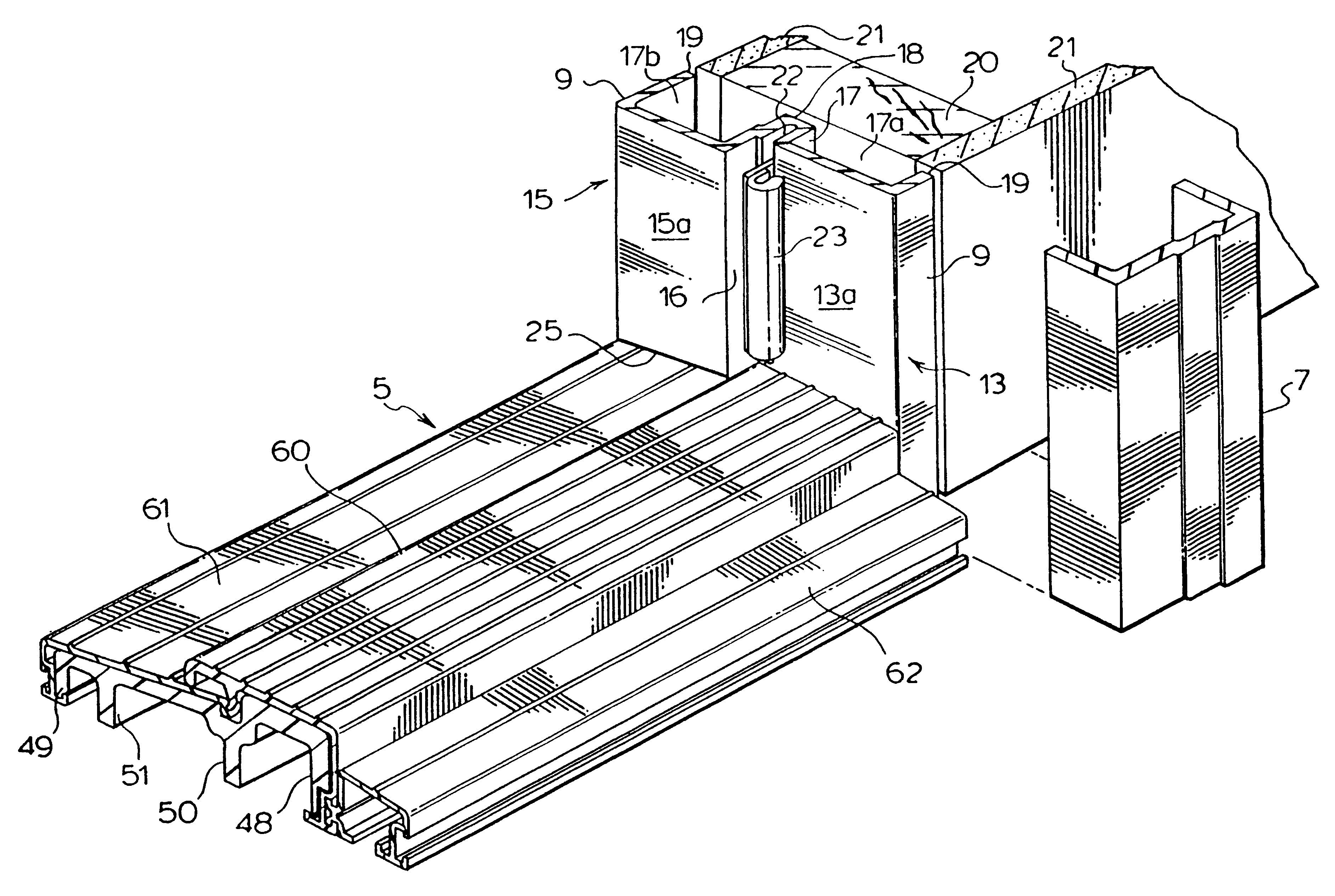
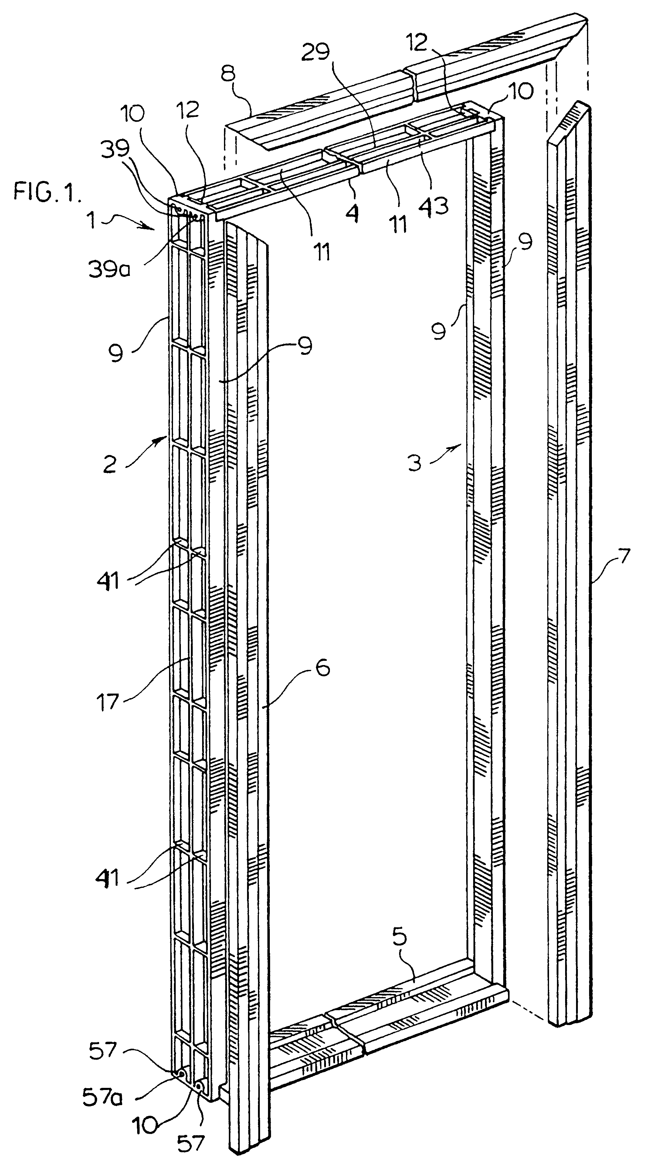
With reference to FIG. 1, there is shown a door frame generally designated at 1 comprising a left hand jamb 2, a right hand jamb 3, a header 4, and a sill 5.

Also in FIG. 1 there is shown a separate trim or brick molding for attachment to the frame 1 comprising a left hand molding jamb 6, a right hand molding jamb 7, and a molding header 8.

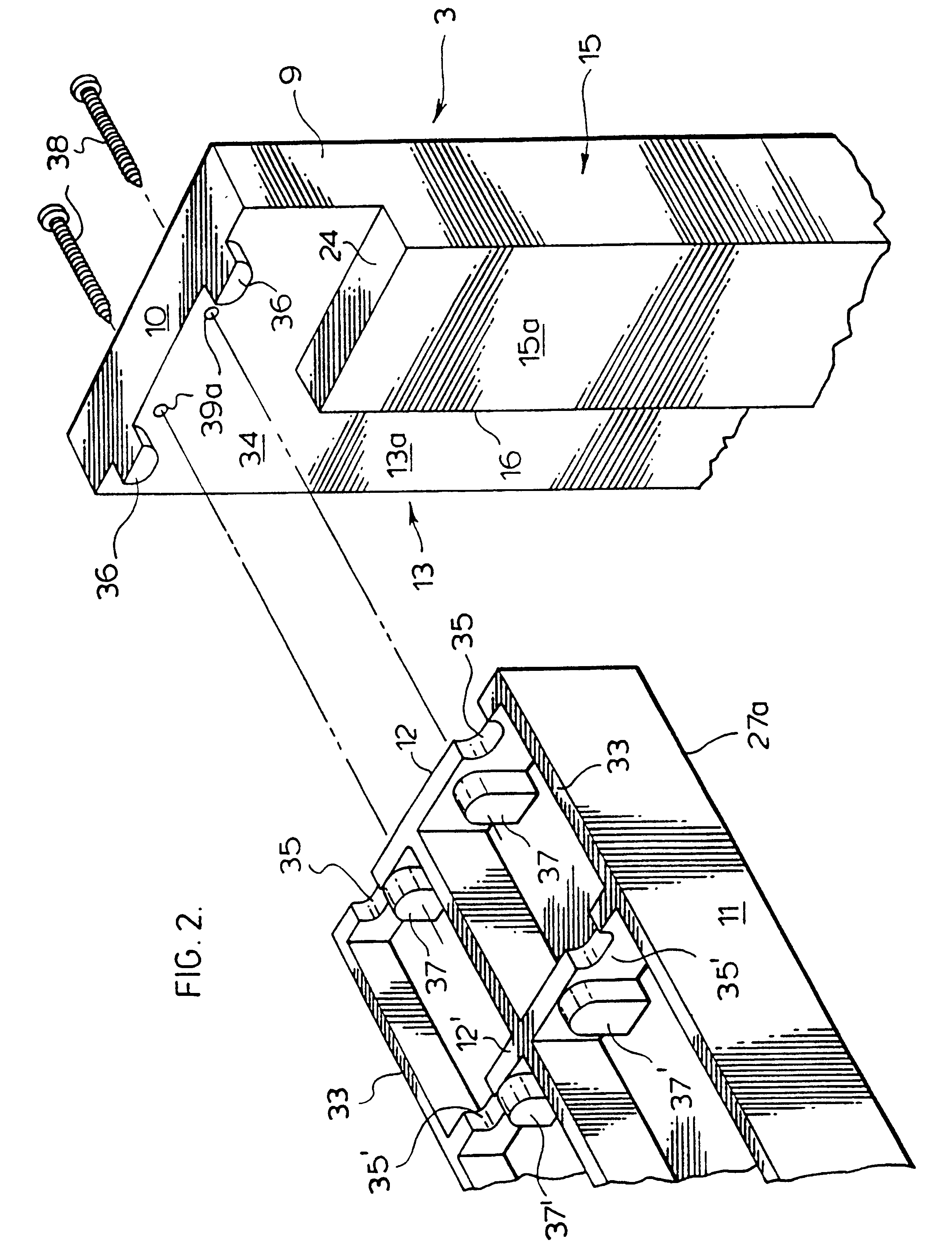
Each of the door frame jambs 2 and 3, header 4, and sill 5 are formed of synthetic material comprising compression moldings of filler, waste, or recycled particulate material bonded together by a thermoplastic binder which advantageously is a waste or a recycled thermoplastic. Similarly, each of the molding members 6, 7 and 8 are also compression moldings of similar synthetic material.

The particulate material to be used in the door frame members is selected to provide the requisite properties such as temperature stability, strength, and hardness.

Where the door frame is to be exposed to substantial temperature changes, the particulate filler, waste,...


PUM

PropertyMeasurementUnit
widthaaaaaaaaaa
widthaaaaaaaaaa
widthaaaaaaaaaa

Abstract

A frame assembly (1) for mounting doors and the like comprising a pair of jambs (2, 3) and a header (4) for connecting said jambs, and, where required, a sill, each said jambs and header and sill (5) where required being a compression molding of filler, waste, or recycled particulate material bound together by a thermoplastic binder, each said jambs (2, 3) and header (4) presenting when assembled an inwardly facing planar surface of a width to receive a door to be mounted in said frame assembly and an inwardly projecting door stop shoulder formation projecting inwardly of said planar surface.

Description

This invention relates to frames for doors and to the frame members from which said frames are assembled.At present, the majority of door frames are made of wood and include a pair of jamb members and a header. If it is an outside door, the door frame also includes a door sill while in the case of inside doors the jambs extend to the floor.Where large volumes are involved, the door frame members can be manufactured at a factory ready to be assembled on the job site or, in some instances, at the factory. Frequently, however, the door frame members are cut from lumber on the job site and drilled and routed out to provide for keepers and hinge mounting areas and then fitted into position for each individual door.In addition to wood, there are door frames of other material or of other material along with wood.U.S. Pat. No. 1,606,780, issued Nov. 16, 1926, discloses a metal door frame.U.S. Pat. No. 4,281,481, issued Aug. 4, 1981, discloses an aluminum door frame while U.S. Pat. No. 3,287...

Claims


Application Information

Patent Timeline
Patent Type & Authority Patents(United States)
IPC IPC(8): E06B1/04E06B1/52E06B1/30E06B3/96E06B1/70
CPCE06B1/30E06B1/52E06B3/96E06B2001/707Y10S49/02
Inventor DE ZEN, VIC
Owner ROYAL GRP TECH LTD
Why Eureka
Try Eureka