Filler assembly for automobile fuel tank

a fuel tank and assembly technology, applied in the direction of container discharging methods, transportation items, transportation and packaging, etc., can solve the problems of extreme injury or death, distorted, or partially crushed fuel tanks that are mounted in the rear of an automobile and under a portion of a back seat, and passengers in the vehicle are injured or killed, and passengers are injured or killed

Inactive Publication Date: 2002-07-09
FENTON RONALD L +1
View PDF19 Cites 28 Cited by
  • Summary
  • Abstract
  • Description
  • Claims
  • Application Information

AI Technical Summary

Problems solved by technology

It is well known that fuel tanks that are mounted in the rear of an automobile and beneath a portion of a back seat and within a portion of or below a trunk compartment of the automobile often are distorted, ruptured, or partially crushed upon impact by another vehicle in a rear-end collision.
In such a rear-end collision, the impact ruptures the fuel tank and fuel is caused to splash or slosh around and move forwardly into the rear seat compartment and even further forward.
Oftentimes, a spark or heat generated from the impact will ignite the fuel causing burning and explosion of the vehicle and resulting in extreme injury, and even death, to passengers in the vehicle.
Fuel tanks when subjected to collisions, have a tendency to explode and / or when crushed from the force of an impact, to open up in such a way that fuel is splashed or spewed up and out of the tank so that any source of ignition (from a spark, heat, raised temperature, etc.) causes the fuel to ignite outside of the fuel tank causing extreme injury or death to passengers.
Automobile companies in a series of rear end collision deaths of fuel tanks showed that the top of some fuel tanks are pried open by the impact and a "Teepee" is created in the middle causing the fuel to splash out of the exposed top and sides of the fuel tank splashing forward and igniting, resulting in severe injury to occupants of the vehicle.

Method used


Image

  • Filler assembly for automobile fuel tank
  • Filler assembly for automobile fuel tank
  • Filler assembly for automobile fuel tank

Examples


Embodiment Construction

)

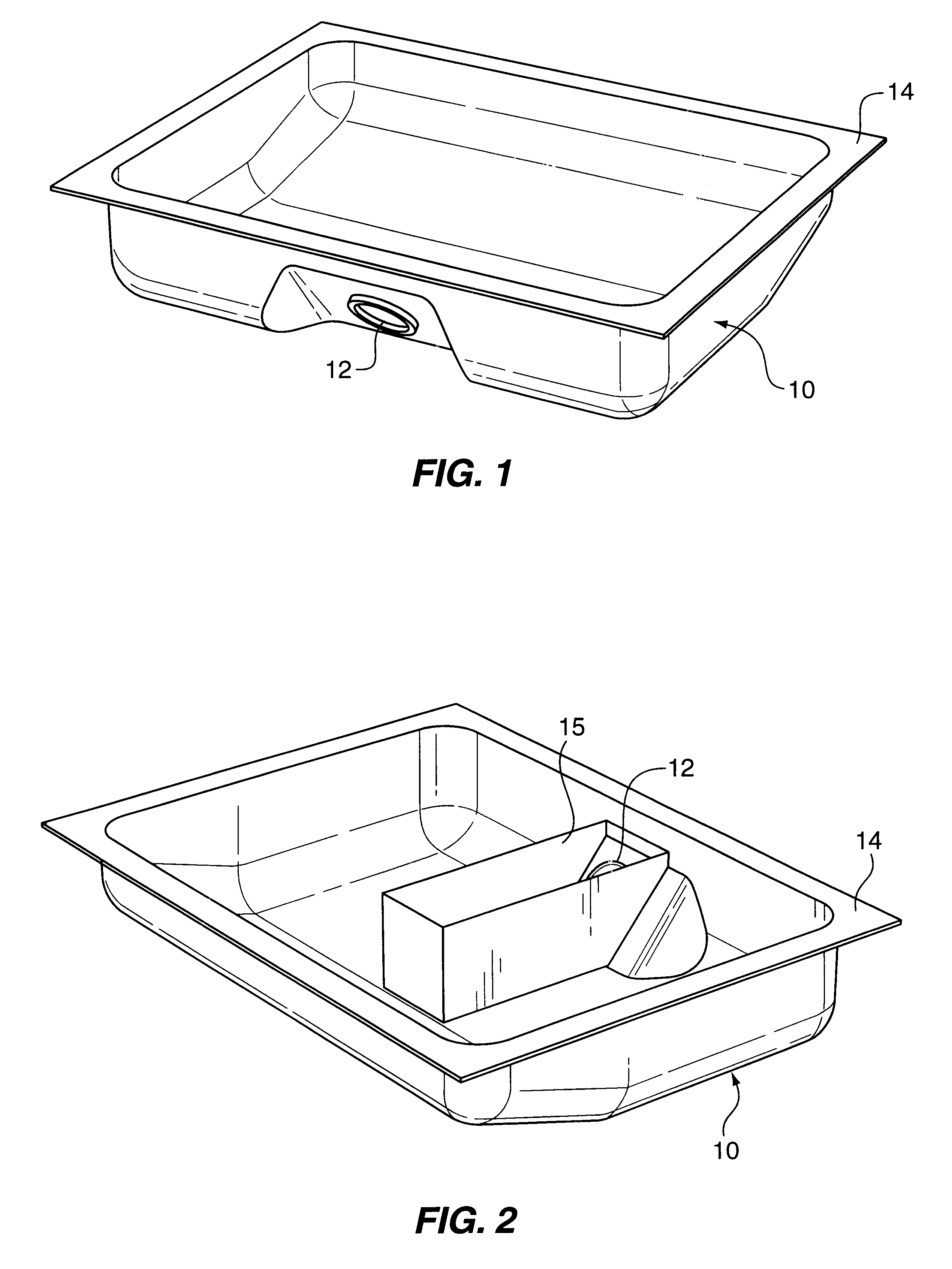
Referring now to the drawings in greater detail, there is disclosed in FIG. 1 a fuel tank bottom portion 10 (hereinafter simply the fuel tank 10) having an inlet opening 12 and a top peripheral flange 14.

As shown in FIG. 2, when the fuel tank 10 is turned around, the opening 12 faces rearwardly for connection to a hose leading to the fuel inlet on the side of the automobile and such opening is surrounded by a generally rectangular or box shaped trough or cage 15 for receiving a float of a fuel gauge and a fuel outlet tube.

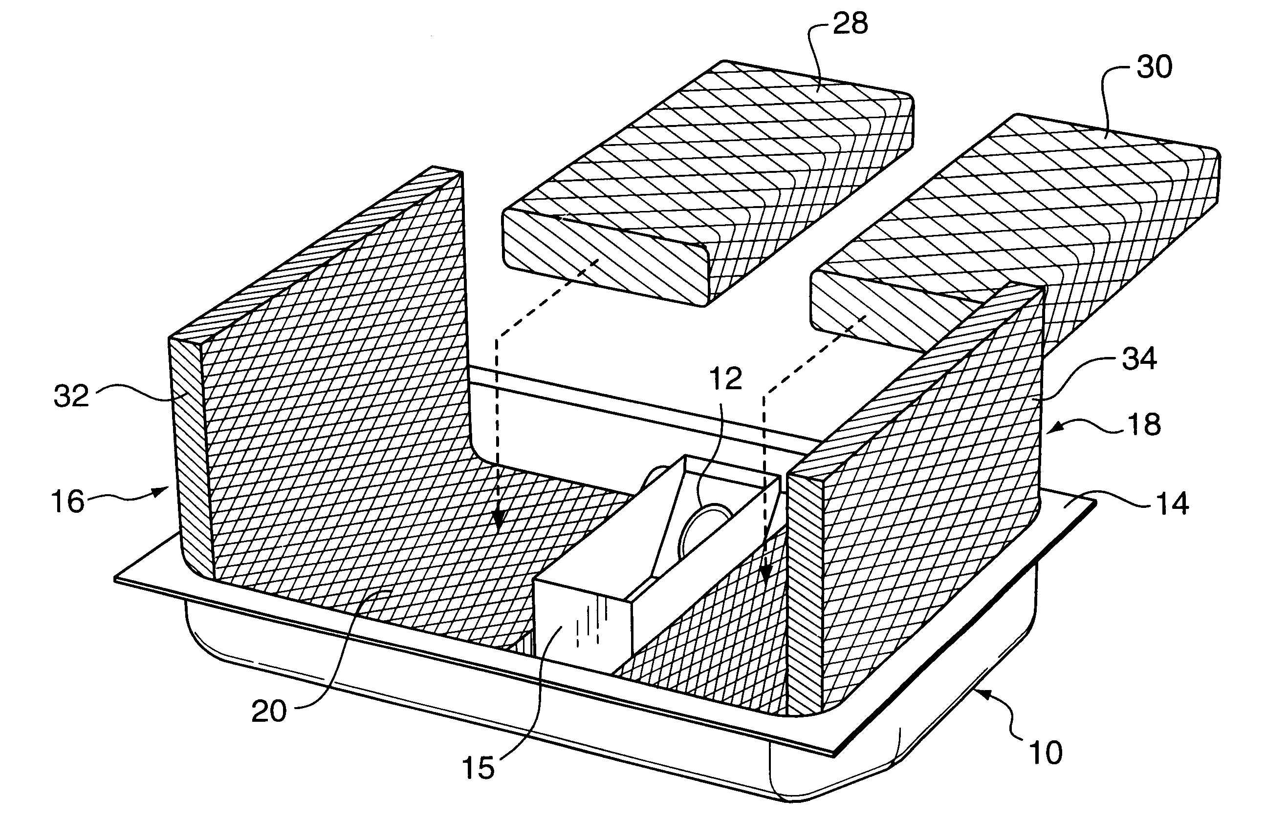
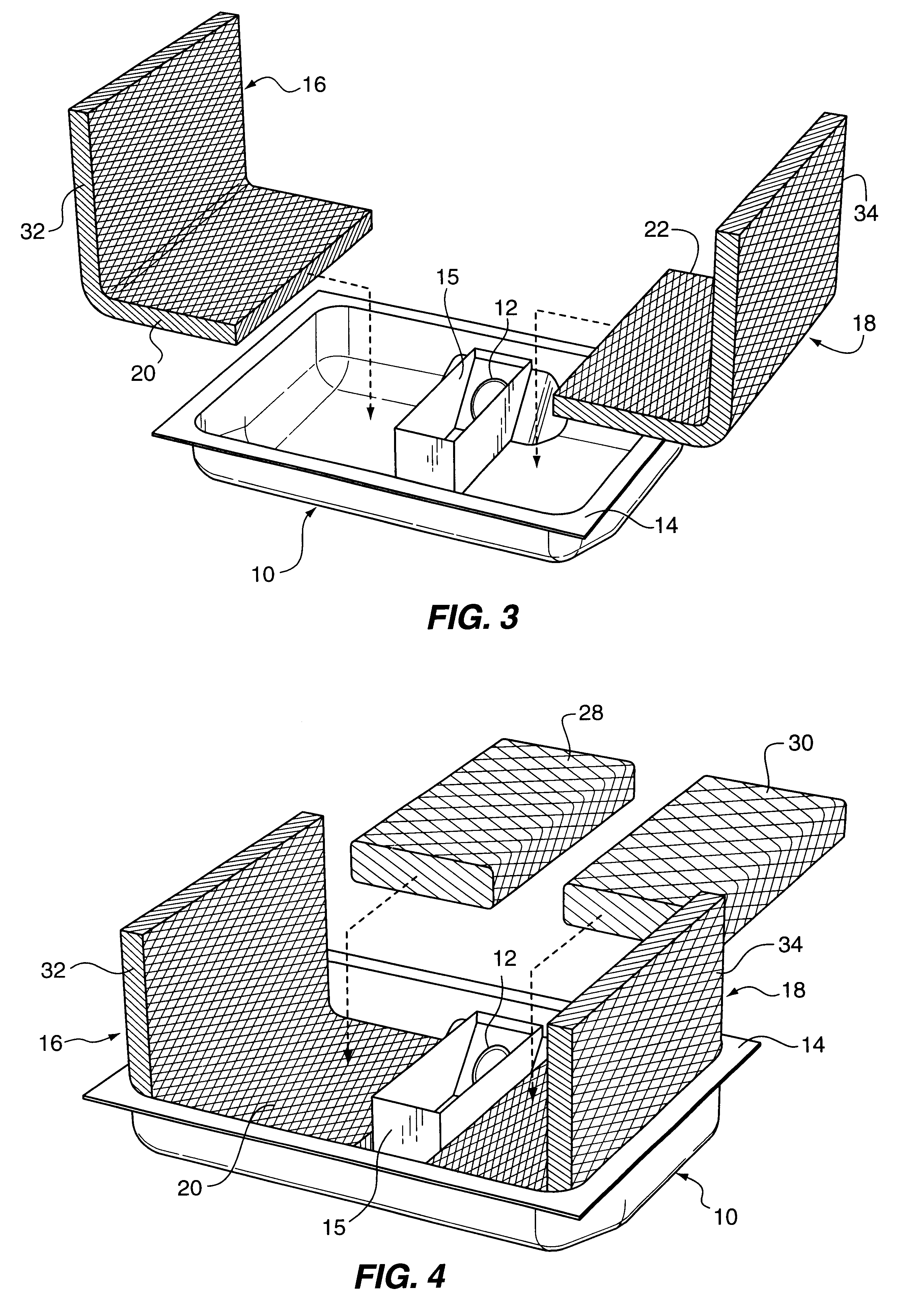
Referring now to FIG. 3, first and second elongate, generally rectangular filler packets 16 and 18 each made of two to ten layers of metal, e.g., aluminum, foil mesh material are folded so as to form a bottom portion 20 or 22 which is inserted into one side 24 or 26 of the tank 10 on each side of the trough or cage 14.

Then, as shown in FIG. 4, two rectangular blocks 28 and 30, each made of several layers of metal foil mesh material having a larger mesh size then t...


PUM


Abstract

The fuel tank assembly for an automobile comprises a substantially box-shaped bottom portion having a top peripheral flange; several highly porous filler packets or blocks made from metal foil mesh material received in the tank, each packet being formed from two to ten layers of metal foil mesh material, and some of said packets being folded over, thereby to substantially fill the tank with the highly porous packets or blocks, and a top tank cover plate sealed to the top peripheral flange. The method for constructing an anti-fuel-splashing and anti-rupturing automobile fuel tank comprises the steps of: providing a generally box-shaped fuel tank bottom portion having a top peripheral flange; providing in the tank a generally trough or cage shaped enclosure surrounding an inlet to the fuel tank; providing a plurality of packets or blocks, some of which are foldable, and which are made of two to ten layers of a metal foil mesh material; and, inserting the packets or blocks into the fuel tank to substantially fill said fuel tank with said packets or blocks made of layers of metal foil mesh material and sealing a cover plate to the top peripheral flange to complete construction of the fuel tank.

Description

1. Field of the InventionThe present invention relates to a filler assembly for an automobile fuel tank where the filler assembly includes packets or blocks made of layers of folded or unfolded sheets of metal foil mesh which are inserted into a fuel tank for dissipating heat and for minimizing sloshing of fuel when the fuel tank is subjected to an impact sufficient to crush a portion of the fuel tank.2. Description of the Prior ArtIt is well known that fuel tanks that are mounted in the rear of an automobile and beneath a portion of a back seat and within a portion of or below a trunk compartment of the automobile often are distorted, ruptured, or partially crushed upon impact by another vehicle in a rear-end collision. In such a rear-end collision, the impact ruptures the fuel tank and fuel is caused to splash or slosh around and move forwardly into the rear seat compartment and even further forward. Oftentimes, a spark or heat generated from the impact will ignite the fuel causin...

Claims


Application Information

Patent Timeline
Patent Type & Authority Patents(United States)
IPC IPC(8): B60K15/077
CPCB60K15/077B60K2015/03381B60K2015/0775Y10T137/86212
Inventor FENTON, RONALD L.SHAKUN, WALLACE
Owner FENTON RONALD L
Why Eureka
Try Eureka