Liquid discharging apparatus
a liquid discharging apparatus and pump technology, applied in the direction of liquid handling, instruments, caps, etc., can solve the problems of high cost of molds for manufacturing cylindrical stoppers and complex shape of cylindrical stoppers
- Summary
- Abstract
- Description
- Claims
- Application Information
AI Technical Summary
Benefits of technology
Problems solved by technology
Method used
Image

Examples
first embodiment (
FIGS. 1 to 4):
A liquid discharging apparatus according to a first embodiment of the invention is now described with reference to FIGS. 1 to 4.
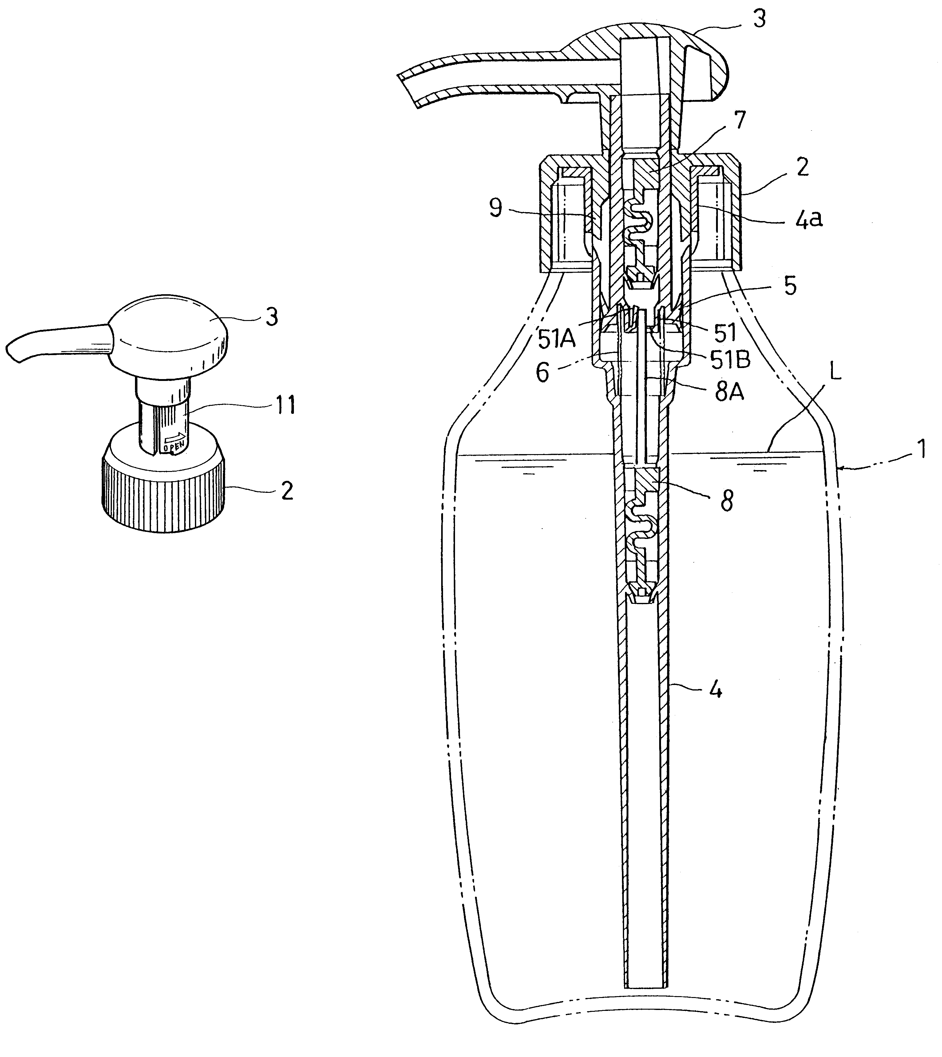
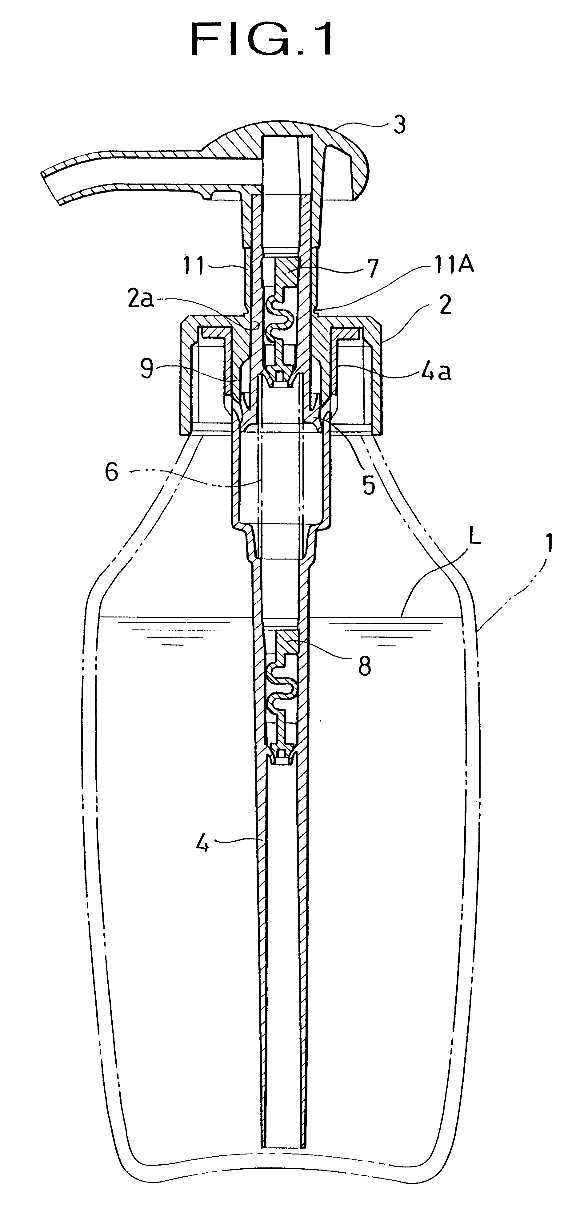
FIG. 1 shows the entire construction of the liquid discharging apparatus. The liquid discharging apparatus in FIG. 1 is held virgin, namely, in an unused state by a virgin seal body, described later.
In FIG. 1, depicted by 1 is a container in which a liquid L is contained, 2 is a cap attached to the opening of the container 1, 3 is a nozzle head that is mounted on the cap 2 to be movable up and down together with a piston 5. When the nozzle head 3 is moved up and down, the liquid L in the container 1 can be discharged outside.
Depicted by 4 is a housing connected to the inner side of the cap 2 and hung down in the container 1. The piston 5 is integrated with the lower part of the nozzle head 3 and movable up and down together with the nozzle head 3. Depicted by 6 is a spring for urging the piston 5 upward, 7 is a valve mounted inside the piston ...
second embodiment (
FIGS. 5 and 6)
A liquid discharging apparatus according to a second embodiment of the invention is now described with reference to FIGS. 5 and 6.
Components which are the same as those of the first embodiment of the invention as shown in FIGS. 1 to housing 4 are depicted by the same reference numerals.
second embodiment
FIG. 5, FIG. 6(A) and FIG. 6(B) show a modification of another virgin seal body, namely, second embodiment of the invention. In the second embodiment, the virgin seal body 11 has a tab T serving as a pinch portion 13 and extended therefrom at the opened portion of the vertical slit 12 so as to be easily pinched.
If the tab T is pulled by fingers, the virgin seal body 11 is easily removed from the cap 2 [FIG. 6(A).fwdarw.FIG. 6(B)]. If the tab T has an irregularity having vertical strips or ribs, it can be easily pinched by fingers with high efficiency. In the second embodiment of the invention, the notch 11B is also provided on the part of the thin portion 11A so as to be caught by fingers for the preparation of separation, whereby the virgin seal body 11 is easily separated from the cap 2.
With the arrangement of the liquid discharging apparatus set forth above, it has the virgin seal body 11 integrated with the cap 2. When the parts or components are assembled, the virgin seal body ...
PUM
 Abstract
Description
Claims
Application Information
 - R&D
- Intellectual Property
- Life Sciences
- Materials
- Tech Scout
- Unparalleled Data Quality
- Higher Quality Content
- 60% Fewer Hallucinations
Browse by: Latest US Patents, China's latest patents, Technical Efficacy Thesaurus, Application Domain, Technology Topic, Popular Technical Reports.
© 2025 PatSnap. All rights reserved.Legal|Privacy policy|Modern Slavery Act Transparency Statement|Sitemap|About US| Contact US: help@patsnap.com