Buckle with smooth tongue insertion mechanism

a technology of insertion mechanism and buckle, which is applied in the direction of belt control system, fastening, garment fastener, etc., can solve the problem of not always satisfying the manipulation feeling of inserting the tongue 73

Inactive Publication Date: 2002-08-06
JOYSON SAFETY SYST JAPAN KK
View PDF18 Cites 10 Cited by
  • Summary
  • Abstract
  • Description
  • Claims
  • Application Information

AI Technical Summary

Problems solved by technology

Consequently, in the conventional buckle, the manipulation fe

Method used


Image

  • Buckle with smooth tongue insertion mechanism
  • Buckle with smooth tongue insertion mechanism
  • Buckle with smooth tongue insertion mechanism

Examples


Embodiment Construction

An embodiment of the present invention will be described below with reference to the drawings.

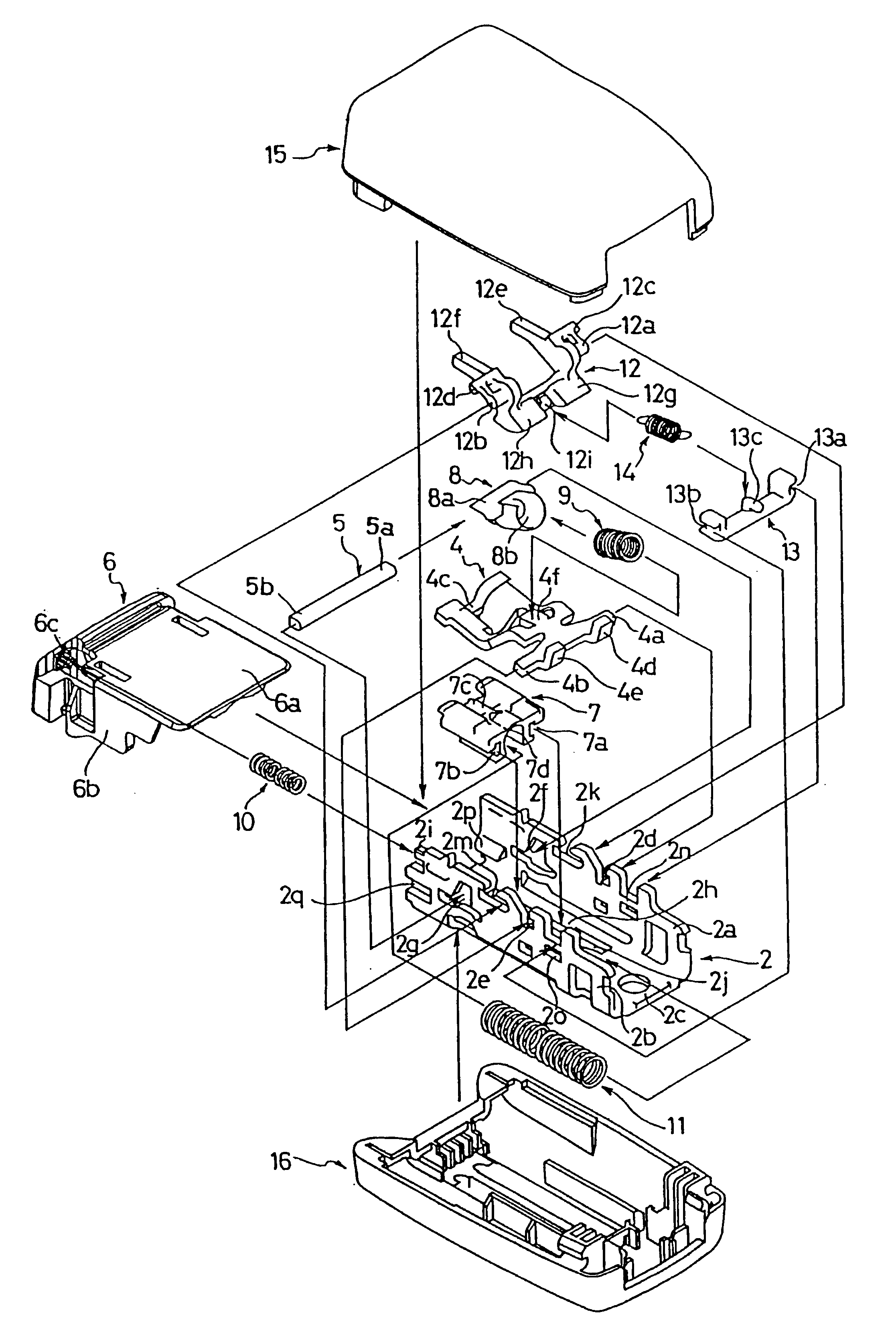
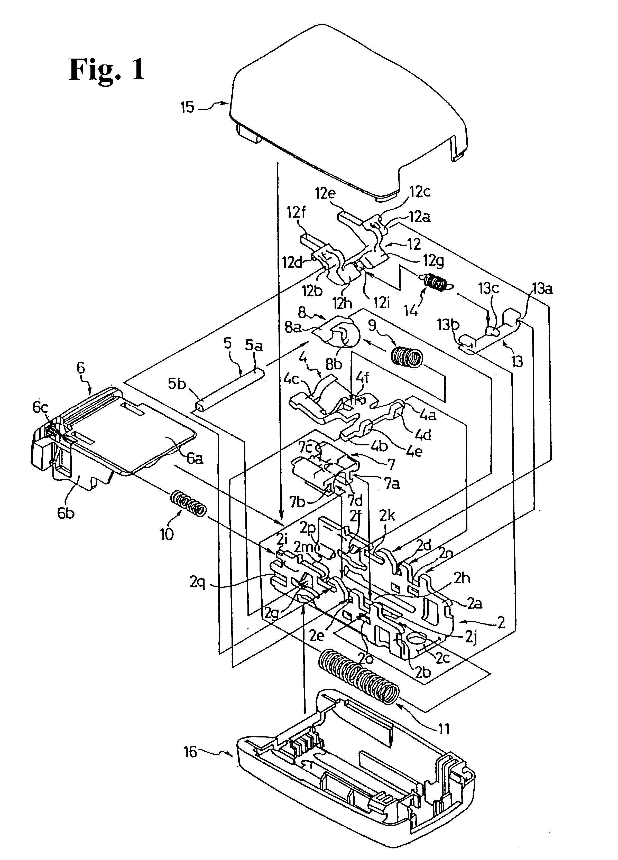
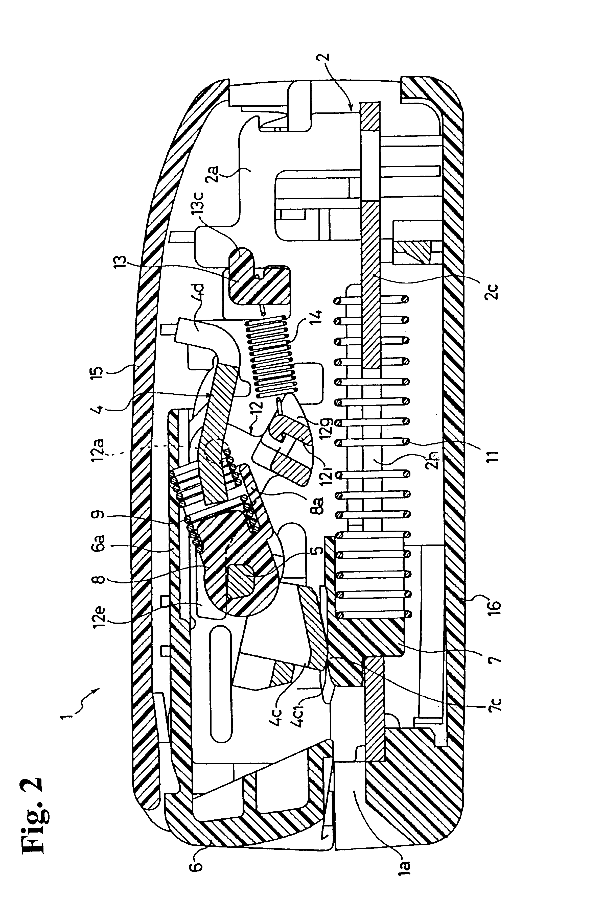
FIG. 1 is an assembly view of a buckle according to an aspect of the present invention. FIG. 2 is a sectional view of the buckle of this embodiment when a tongue is not latched. FIG. 3 is a sectional view of the buckle of this embodiment when the tongue is latched. FIG. 4 illustrates a guide opening, a support and a guide groove disposed in a side wall of a base of this embodiment. The words "right" and "left" used in the description hereinafter indicate the right and left as viewed in the Figures.

As shown in FIGS. 1 to 4, a buckle 1 of this embodiment comprises a base 2 having a U-shaped frame with two side walls 2a, 2b and a bottom 2c; a latch member 4 which is pivotally supported by the side walls 2a, 2b of the base 2, for latching a tongue 3; a lock pin 5 movably disposed to the two side walls 2a and 2b of the base 2, for preventing the latch member 4 from moving in the direction which ...


PUM


Abstract

A buckle is formed of a base having two side walls, a cover for accommodating and supporting the base, and having a tongue insertion hole formed at one end side of the two side walls of the base, and guide portions provided on each of the two side walls to protrude inwardly therefrom for leading a tongue to be inserted through the tongue insertion hole. The guide portions lead a tip of the tongue smoothly without blocking even when the tongue is inserted from the tongue insertion hole at a maximum slant posture defined by the tongue insertion hole relative to the buckle. The tongue can be smoothly inserted into the buckle to improve the manipulation feeling in inserting the tongue.

Description

BACKGROUND OF THE INVENTION AND RELATED ART STATEMENTThe present invention relates to a buckles for use in safety belt device, such as seat belt device, mounted on a seat of a vehicle, such as automobile.Recently, on the seats of various types of vehicles, typically automobiles, seat belt devices are mounted to protect the vehicle occupants in case of emergencies, such as collisions. In order to readily fasten and unfasten the seat belt device of this type, normally there is provided a buckle which includes a latch member having a joggle unit for latching a tongue, the latch member being biased by a spring in a direction which allows latching of the tongue.When the tongue is inserted from a tongue insertion hole of the buckle, the tip of the tongue is led inside by guide units provided on two side walls of a base of the buckle.FIG. 7 is a schematic view of a conventional guide unit.As shown in FIG. 7, on two side walls 71a of a base 71, guide units 72 are formed to protrude inward. ...

Claims


Application Information

Patent Timeline
IPC IPC(8): A44B11/25B60R22/48
CPCA44B11/2523Y10T24/45623Y10T24/45639Y10T24/45665Y10T24/4566
Inventor YAMAGUCHI, YUTAKASHIOTA, AKIHIROKAWAI, YOSHIHIKOASAKO, TADAYUKIKIMURA, TAKAAKI
Owner JOYSON SAFETY SYST JAPAN KK
Why Eureka
Try Eureka