
Low profile, broad band monopole antenna with inductive/resistive networks

Inactive Publication Date: 2002-08-06
SHAKESPEARE CO
View PDF10 Cites 31 Cited by
  • Summary
  • Abstract
  • Description
  • Claims
  • Application Information

AI Technical Summary

Benefits of technology

It is yet another object of the present invention to provide an antenna, as set forth above, which provides high voltage protection of up to 20 KV rms 60Hz for personnel and equipment should a tip portion of a vehicle-mounted antenna's radiator come in contact with high voltage power lines.
It is still yet another object of the present invention, as above, to connect the unun transformer to a linear radiator and a parallel inductor-resistor network to assist in regulating the effective electrical length of the antenna.
It is yet another object of the present invention, as above, to connect the first inductor-resistor network to an additional linear radiator and a second parallel inductor-resistor network to further assist in adjusting the effective electrical length of the antenna.

Problems solved by technology

Unfortunately, the useful bandwidths for this type of antenna are very narrow, usually on the order of KHz or 2-3 MHz.
However, the number of traps is usually limited to 2 or 3.
Nor is there available an antenna with such a wide bandwidth that also has a relatively low VSWR across the bandwidth.

Method used


Image

  • Low profile, broad band monopole antenna with inductive/resistive networks
  • Low profile, broad band monopole antenna with inductive/resistive networks
  • Low profile, broad band monopole antenna with inductive/resistive networks

Examples


Embodiment Construction

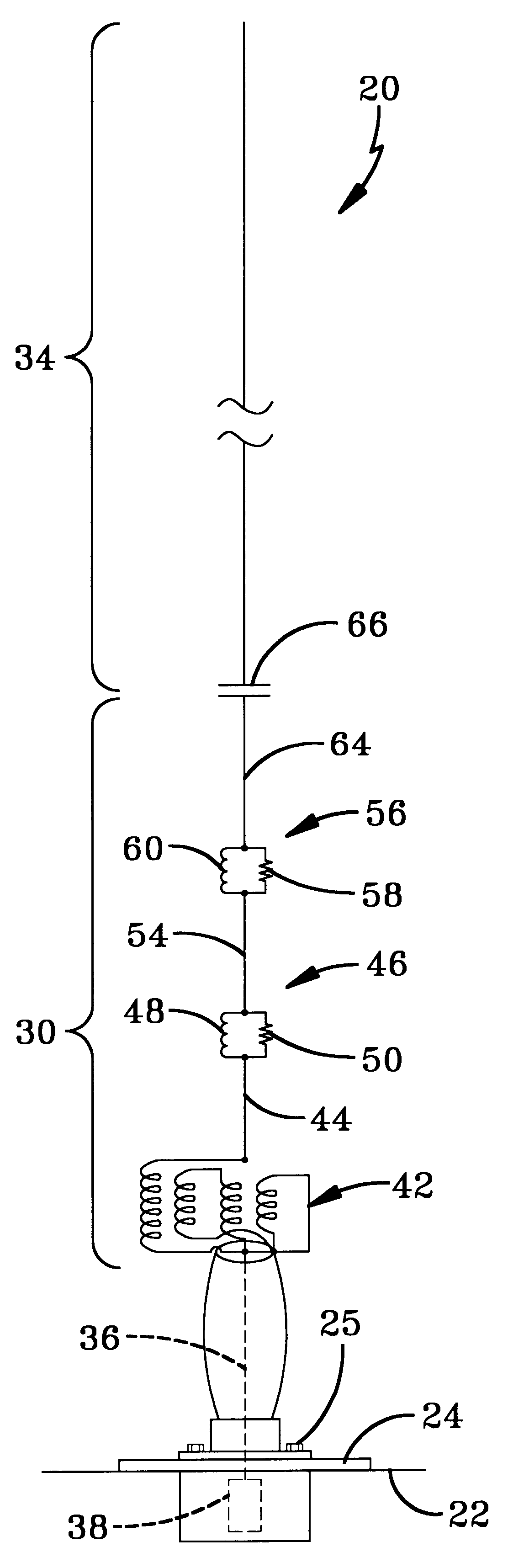
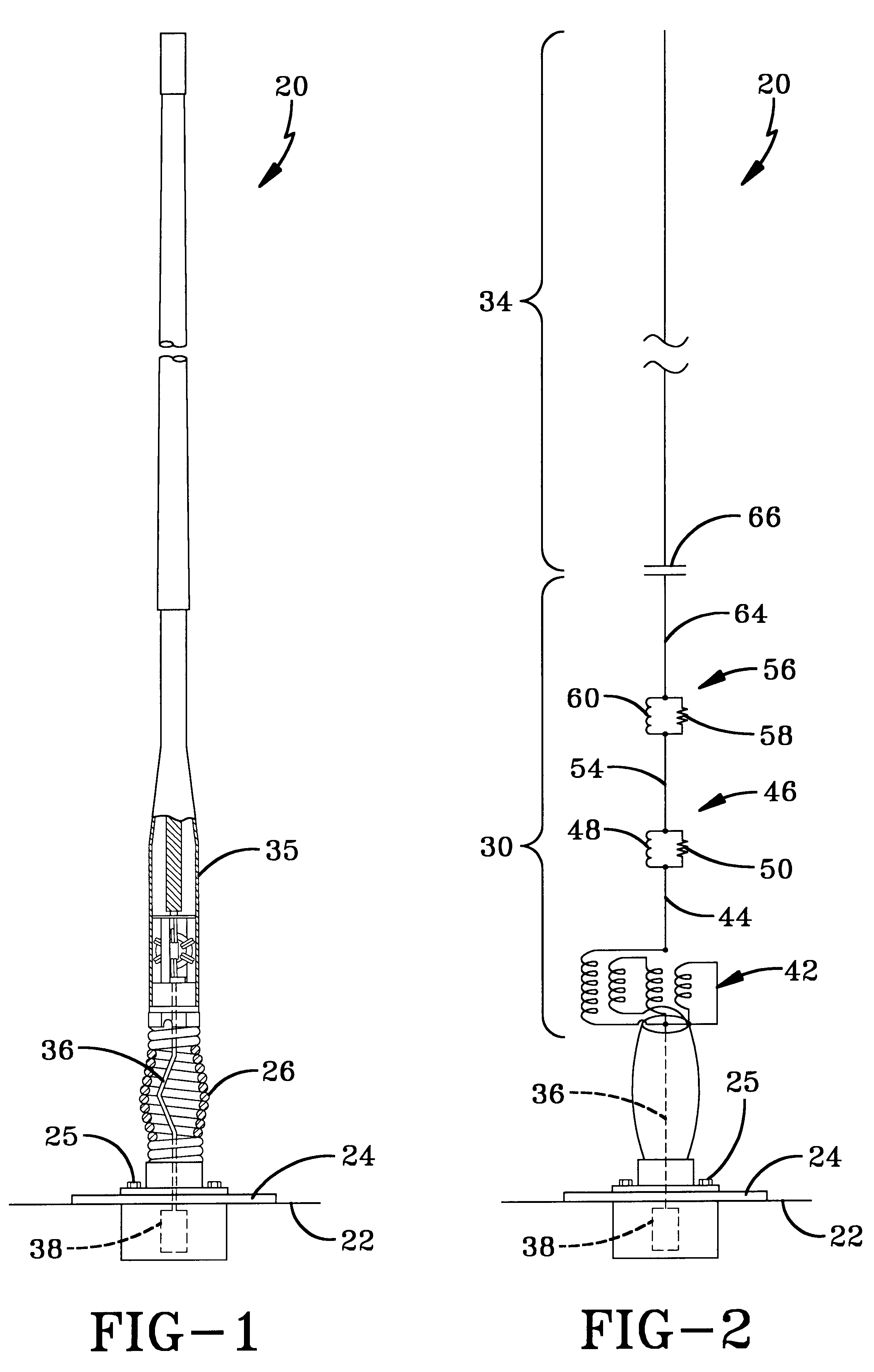
Referring now to the drawings and, in particular, to FIGS. 1 and 2, a broad band antenna according to the present invention is generally indicated by the numeral 20. The antenna 20 is vertically secured to a mounting plane 22 which provides a sufficient ground plane, such as a military vehicle or the like. The antenna of the preferred embodiment is employed for ground-to-ground, ground-to-air communications, and, as will become apparent later, for satellite communication. The antenna 20 is secured to the mounting plane 22 by a base plate 24 with a plurality of fasteners 25 in a manner well known in the art. Extending substantially vertically from the base plate 24 is a spring assembly 26 which provides a flexible mounting for the antenna 20. The spring assembly 26 is preferably made of a corrosion-resistant steel, and is mechanically connected to the base plate 24 and the components of the antenna so as to withstand any flexure forces applied to the antenna.

Extending vertically from...


PUM


Abstract

An antenna (20) operable over a predetermined range of frequency includes a transmission line (36), a transformer network (42) connected to one end of the transmission line, and at least one inductor-resistor network (46) connected to an opposite end of the transformer network. The inductor-resistor network (46) changes the effective electrical length of the antenna (20) such that as the frequency of operation changes, the current distribution above and below the inductor-resistor network changes in a corresponding manner. A second inductor-resistor network (56) may be serially connected to the other network (46), wherein both function to reduce the current thereabove. Accordingly, as the frequency of operation increases, the electrical height of the antenna decreases.

Description

The present invention relates generally to antennas used in mobile and / or military applications. More particularly, the present invention relates to a broad band antenna that provides an instantaneous bandwidth of about 482 Megahertz(MHz) between 30-512 MHz with a relatively low voltage standing wave ratio (VSWR) and high gain. Specifically, the present invention provides a monopole broad band antenna with a series of inductor-resistor networks which effectively change the electrical length of the antenna.It is known that electromagnetic communication systems employ broad bandwidth techniques, such as the so-called frequency-agile or frequency-hopping systems in which both the transmitter and receiver rapidly and frequently change communication frequencies within a broad frequency spectrum in a manner known to both units. When operating with such systems, antennas having multiple matching and / or tuning circuits must be switched, whether manually or electronically, with the instantan...

Claims


Application Information

Patent Timeline
IPC IPC(8): H01Q9/30H01Q5/02H01Q5/00H01Q9/04H01Q5/15H01Q5/321
CPCH01Q5/00H01Q5/321H01Q9/30
Inventor LEWIS, JR., JOHN R.
Owner SHAKESPEARE CO
Features
  • Generate Ideas
  • Intellectual Property
  • Life Sciences
  • Materials
  • Tech Scout
  • Unparalleled Data Quality
  • Higher Quality Content
  • 60% Fewer Hallucinations
Learn More