
Ventilation valve with a breathing channel for a tank container of a helicopter

a technology of ventilation valve and tank container, which is applied in the direction of functional valve types, machines/engines, liquid fuel feeders, etc., can solve the problems of improper ventilation and interruption of breathing channels, and the actual capacity of tank containers cannot be fully utilized

Inactive Publication Date: 2002-08-27
AIRBUS HELICOPTERS DEUT GMBH
View PDF8 Cites 23 Cited by
  • Summary
  • Abstract
  • Description
  • Claims
  • Application Information

AI Technical Summary

Benefits of technology

Particularly, the valve ball is a buoyant valve ball that buoyantly floats upward in or on the fuel as the level thereof rises into the first ventilation valve. This causes the valve ball to seal an opening or port from the first ventilation valve into the first breathing channel when the first tank is substantially full with fuel. Preferably, the valve ball can move freely through a stroke path in the hollow cylinder area within the valve housing extending from the safety device to the port opening of the valve into the breathing channel. In order to seal the port opening, the diameter of the valve ball is larger than that of the port opening.
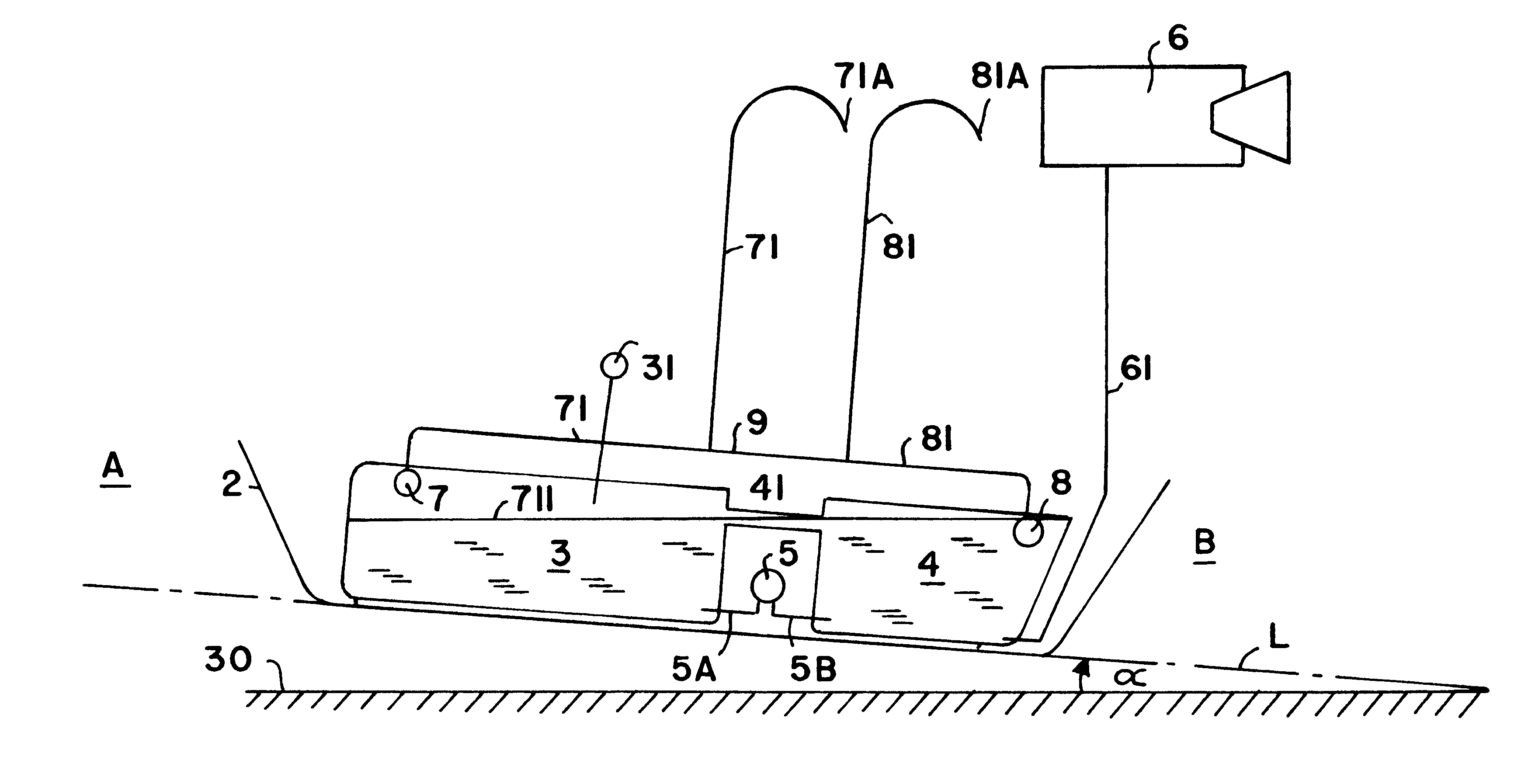
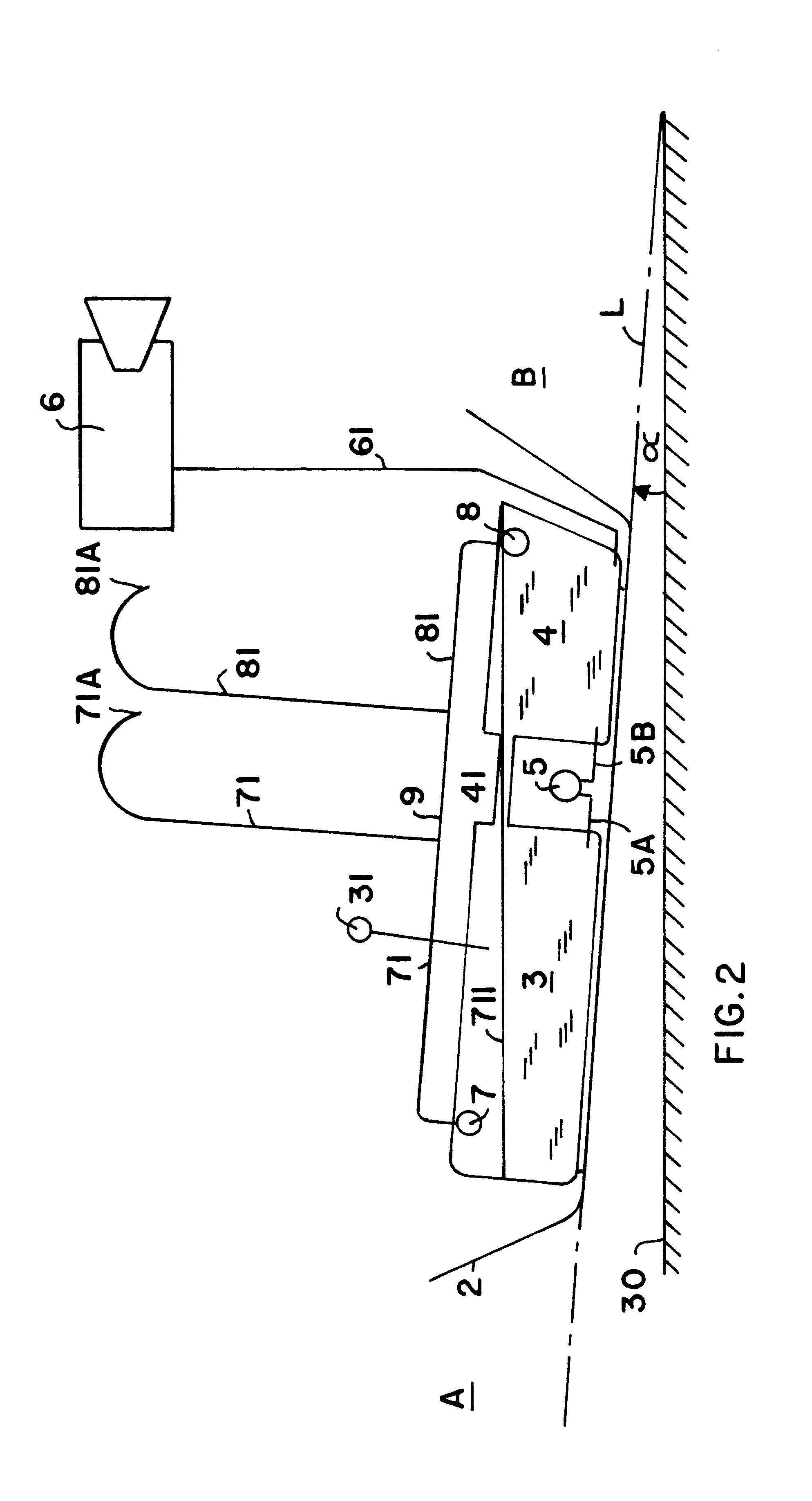
With the inventive arrangement, the tank containers can be filled completely without endangering the breathing of the tank system. The ventilation valve according to the invention is arranged in the extraction tank (i.e. the above mentioned first tank is preferably the extraction tank), while the second tank i.e. the main tank may still be equipped with the prior art ventilation valve. The invention also ensures that condensed fuel will not endanger the breathing or ventilation of the tank system. Even in flight and especially horizontal flight, at least one of the two ventilation channels will be available for the tank system to breath.

Problems solved by technology

The disadvantage of the state of the art arrangement is that the tank container of the helicopter with the prior art ventilation valve cannot be completely filled with fuel, so that the actual capacity of the tank containers cannot be fully utilized even though it is available as empty tank volume.
When the tank container is completely full, this problem also arises in forward horizontal flight when the extraction tank is somewhat higher than the main tank due to the flight position.
When there is too much fuel in the channel, the proper ventilation functioning of the breathing channel can be disturbed or interrupted.

Method used


Image

  • Ventilation valve with a breathing channel for a tank container of a helicopter
  • Ventilation valve with a breathing channel for a tank container of a helicopter
  • Ventilation valve with a breathing channel for a tank container of a helicopter

Examples


Embodiment Construction

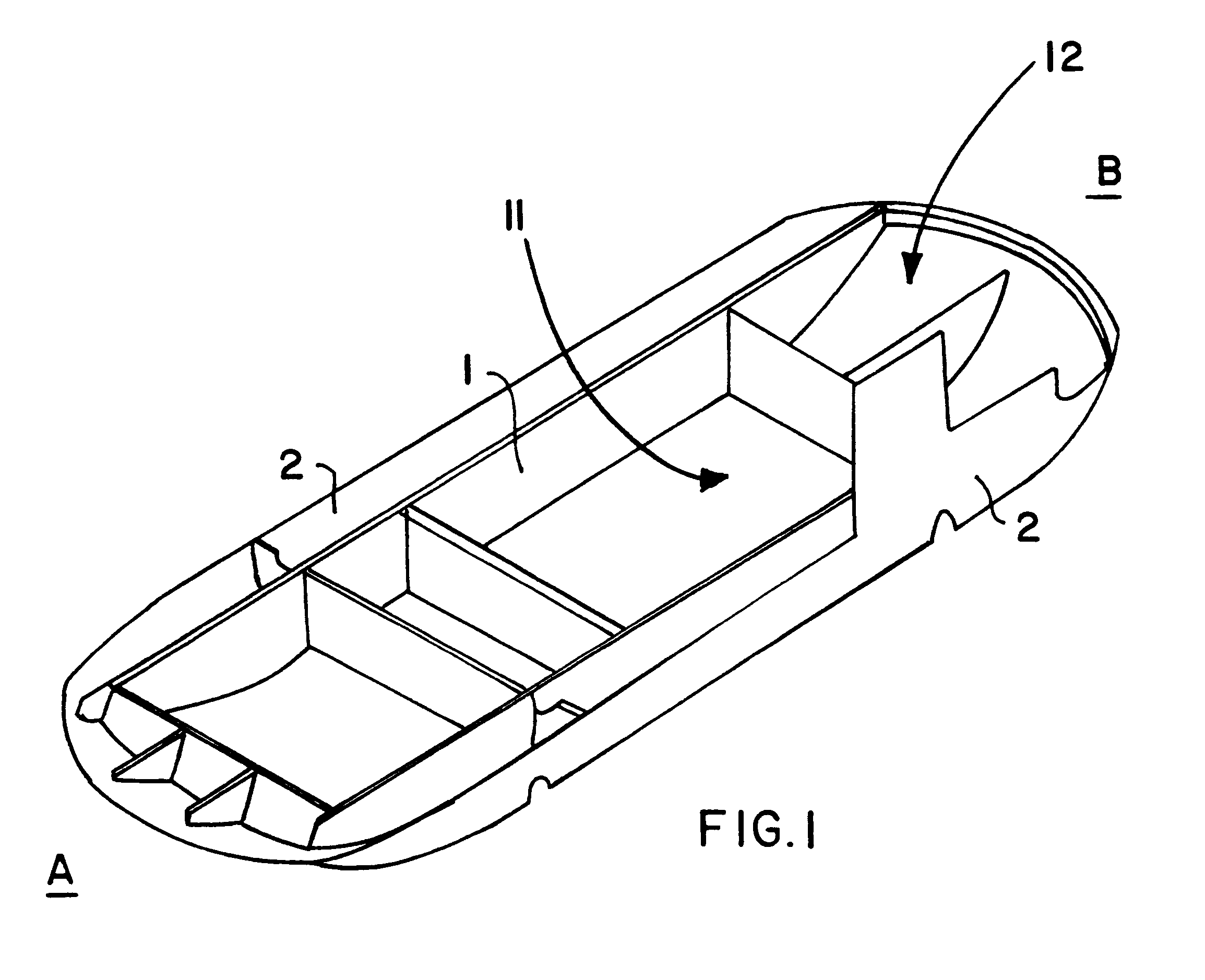
FIG. 1 shows the subfloor structure 1 on the bottom shell 2 of the fuselage of a helicopter. The subfloor structure 1 has several chambers along its length from the tail B to the nose A. The main fuel tank is in chamber 11, and the fuel extraction or discharge tank is in chamber 12. Chamber 12 is at the tail B of the helicopter.

FIG. 2 schematically portrays the angle a of the lengthwise axis L of a helicopter standing on a resting surface 30 such as the ground. The bottom shell 2 represents the outer bottom contour of the helicopter. Lying on the shell 2 are the main tank 3 and the extraction or discharge tank 4. Both tanks are within the subfloor structure 1, i.e. received in the respective chambers between the components thereof (not shown in FIG. 2). The filler neck 31 for filling fuel into the tanks is connected to the main tank 3. A fuel pump 5 with connecting lines 5A and 5B connects the main tank 3 with the extraction tank 4. This ensures that the extraction tank 4 is always ...


PUM


Abstract

A ventilation valve cooperating with a breathing channel for a fuel tank of a helicopter has a safety device arranged in a valve housing of the ventilation valve. To seal the breathing channel from the tank when a connection between the fuselage cell and the tank is released or disrupted, e.g. in a crash, the safety device includes a spring-loaded plunger (15), a retainer (22), and a movable seal element (10). To allow the tank container to be filled essentially full, and to ensure the ongoing reliable functioning of the breathing channel, the seal element (10) is a buoyant valve ball (10) that seals the breathing channel (81) of the fuel extraction or discharge tank (4) if the fuel level (711) in the tank (4) rises up into the valve (8). Also, the breathing channel (81) is connected with the breathing channel (71) of a main fuel tank (3) by a connecting channel (9).

Description

PRIORITY CLAIMThis application is based on and claims the priority under 35 U.S.C. .sctn.119 of German Patent Application 199 44 124.3, filed on Sep. 15, 1999.The invention relates to a ventilation valve with a breathing channel for a tank container and particularly a fuel tank of a helicopter. The ventilation valve contains a device to seal the breathing channel from the tank when a connecting means between the fuselage cell (especially the floor) and the tank container is loosened (as a result of a crash), whereby the device is arranged in a valve housing of the ventilation valve and has a movable seal element.BACKGROUND INFORMATIONMany state of the art helicopters have a tank system that comprises, among other things, two tank containers. Both tank containers, which are also termed the main tank and the extraction tank or fuel feed tank, are arranged within a subfloor structure, whereby the subfloor structure is attached between the floor and the bottom shell of the fuselage. The...

Claims


Application Information

Patent Timeline
IPC IPC(8): B64D37/00B64D37/32B64D37/02B60K15/035B60K15/03B64C27/04B64D37/06F02M37/00F16K24/00
CPCB64D37/02B64D37/32B60K15/03519Y10T137/7873Y10T137/3099
Inventor SCHLEGEL, WERNERWOJATSCHEK, KLAUS
Owner AIRBUS HELICOPTERS DEUT GMBH
Learn More