Arrangement for cabs for vehicles

a technology for cabs and vehicles, applied in the direction of roofs, transportation and packaging, tractors, etc., can solve the problems of complex shock absorbers, expensive springs, and complicated components

Inactive Publication Date: 2002-08-27
SCANIA CV AB
View PDF24 Cites 41 Cited by
  • Summary
  • Abstract
  • Description
  • Claims
  • Application Information

AI Technical Summary

Benefits of technology

The object of the present invention is to provide a solution which has the effect of eliminating the disadvantages mentioned above. This is achieved by the features of the invention which includes the cab being supporting by spring elements relative to the vehicle frame. At least one arm and usually two arms extend between the frame and the cab, following the springing movement of the vehicle cab. There are upper and lower stop surfaces at the frame which limit the springing movement of the cab. One end of the link arm is rotatably arranged relative to a supporting element fastened to the frame. The other end of the link arm is arranged in a resilient bushing, preferably a rubber bushing in the carrier element. The link arm is provided with a movement limiter which extends transverse to the longitudinal direction of the vehicle. The movement limiter extends between the top and bottom stop surfaces so that contact between the movement limiter and the stop surfaces which occurs upon movement of the link arm controls the extent of movement of the link arm and controls the tilting movement of the cab. The stop surfaces may be defined in an aperture extending through a carrier secured to the cab. There may be a stabilizer between the cab and the frame and the link arm may be a side piece of that stabilizer. Shock absorbing material may be provided on the movement limiter to damp the shocks when they move the limiter to contact the stop surfaces.
Applying the invention makes it possible to use a simpler gas spring or shock absorber without built-in endstops. It also makes it possible to use significantly less strong mountings, because the endstops being separate from the gas spring or shock absorber means that the mountings are subject to significantly smaller forces.

Problems solved by technology

In cases where gas springs are used, the endstops are incorporated in the respective springs, which makes the springs expensive and complicated.
Like gas springs, shock absorbers are complicated and require strong mountings capable of absorbing the large forces which occur in the spring arrangement during operation and upon tilting.

Method used


Image

  • Arrangement for cabs for vehicles
  • Arrangement for cabs for vehicles
  • Arrangement for cabs for vehicles

Examples


Embodiment Construction

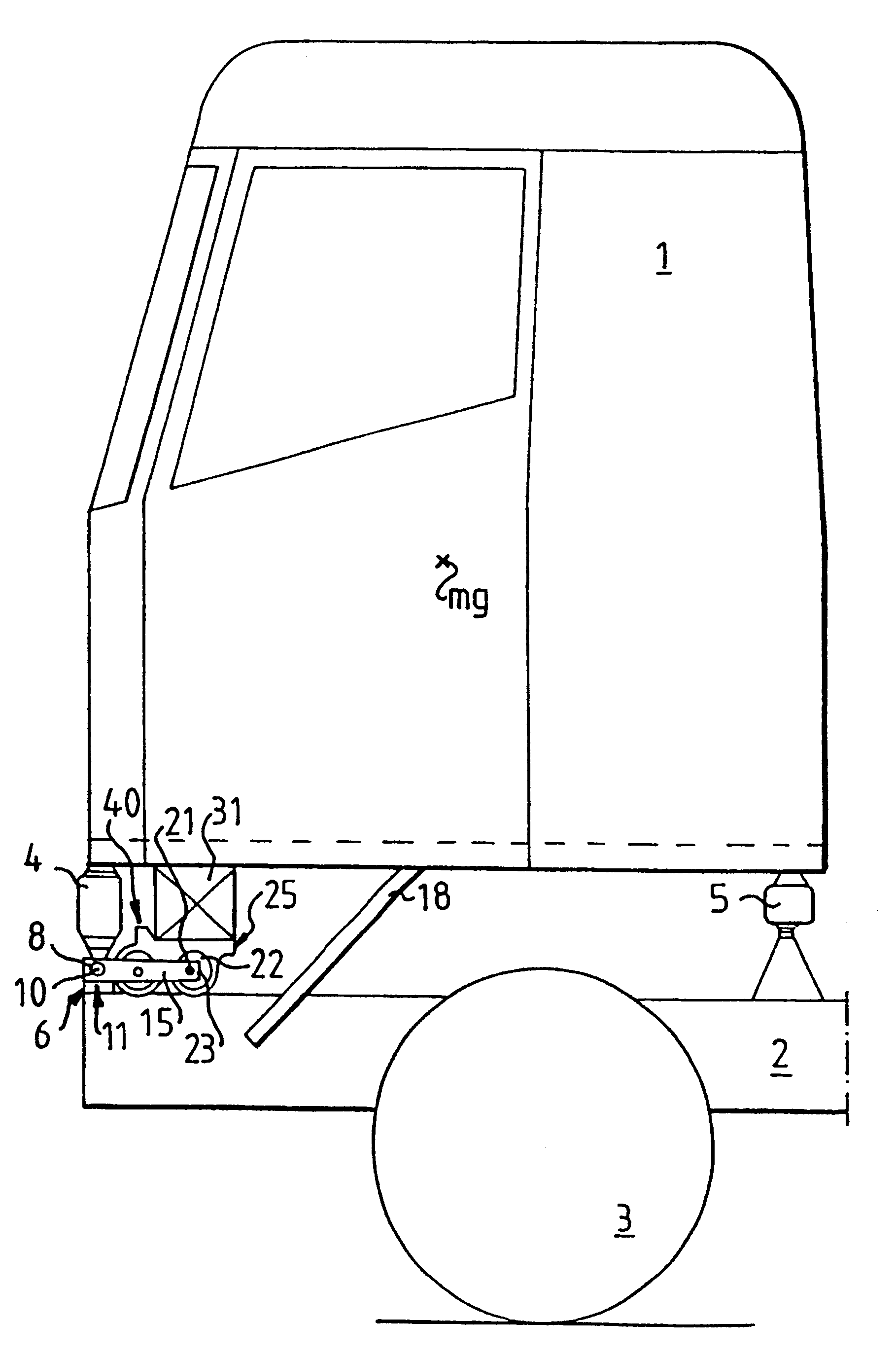
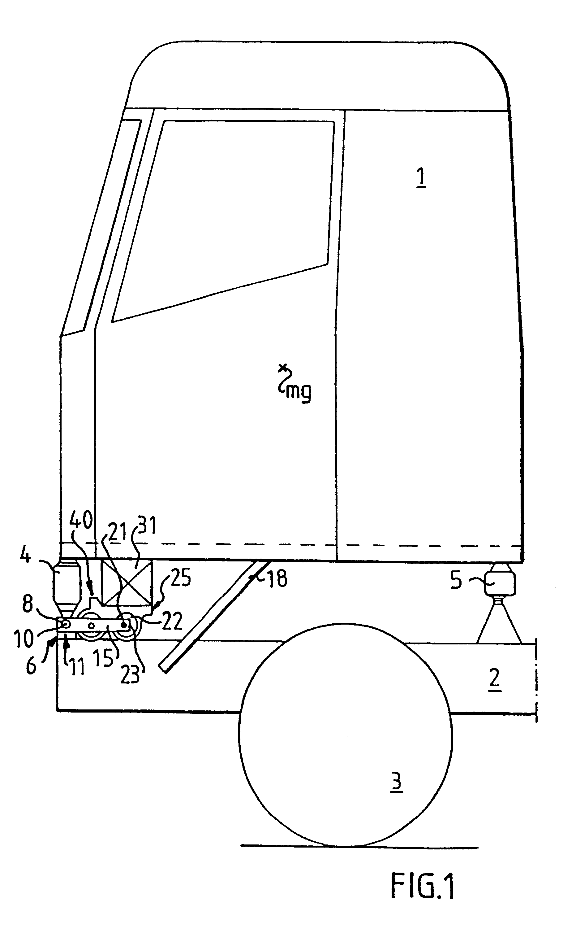
FIG. 1 depicts schematically a sideview of a driving cab 1 for a freight vehicle together with the structure which supports the driving cab 1 on a chassis or frame 2 of the freight vehicle. The front pair of wheels are denoted by reference 3. The driving cab 1 is kept balanced by means of a number of gas springs, comprising in this embodiment two forward gas springs 4 and two rear gas springs 5. Both the rear and the forward gas springs are arranged approximately at the respective corners of the cab 1. The gas springs 4 and 5 are thus placed between the floor of the cab 1 and the frame 2.

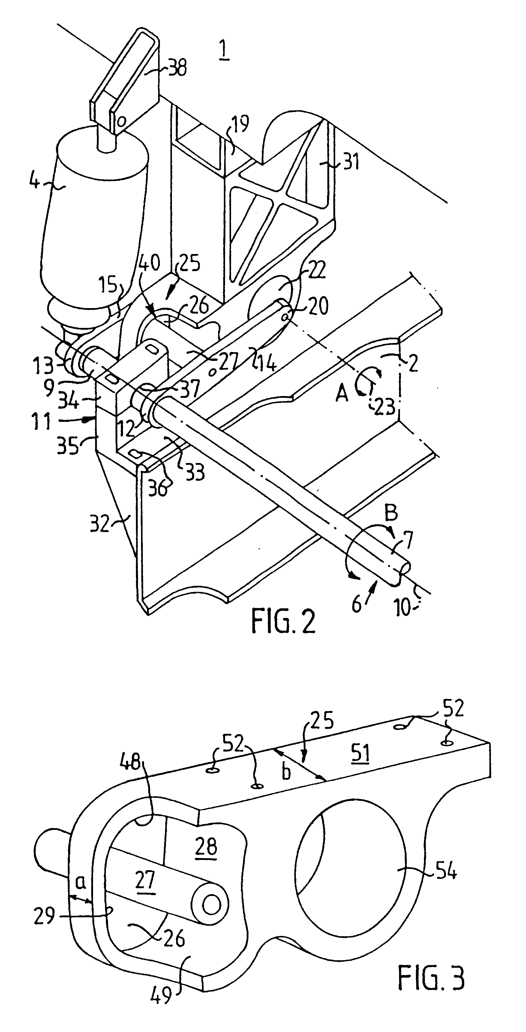
FIGS. 1 and 2 show a stabiliser 6 arranged between the cab 1 and the frame 2 in order to damp cab rolling motions. The stabiliser 6 incorporates a torque bar 7, one end 8 of which is depicted at a front corner of the cab in FIG. 1. The other end 9 of the torque bar 7 is depicted in FIG. 2 and is correspondingly situated at the other front corner of the cab. The torque bar 7 is arranged for rotation ...


PUM


Abstract

A vehicle cab is resiliently suspended on a vehicle frame. Between the cab and the frame is arranged a device for limiting the mobility of the cab relative to the frame during operation and upon tilting of the cab. The device incorporates two stop surfaces fastened to the cab, and a movement limiter fastened to a stabilizer which is fastened to the frame. The movement limiter extends between the stop surfaces so that it shifts between them upon movement of the link arms. The cab's mobility is limited by the fact that contact occurs between the movement limiter and the stop surfaces.

Description

The present invention relates to an arrangement for driving cabs for vehicles of the kind indicated in the preamble to patent claim 1.STATE OF THE ARTA known practice is to arrange springs, e.g. gas springs or coil springs, between the cab and frame of freight vehicles for the sake of greater comfort while the vehicle is in motion. The springs enable the cab to move between upper and lower endstops which limit cab movement relative to the frame not only during operation but also when the cab is tilted forward to render the engine, situated under the cab, accessible for servicing or repair. In cases where gas springs are used, the endstops are incorporated in the respective springs, which makes the springs expensive and complicated. As powerful forces act upon the endstops, particularly when the cab is tilted, strong spring mountings are also required for fastening the gas springs to the cab. The use of coil springs usually entails the use of a separate shock absorber associated with...

Claims


Application Information

Patent Timeline
Patent Type & Authority Patents(United States)
IPC IPC(8): B62D33/06B62D33/067
CPCB62D33/067
Inventor JOHANSSON, DANIELOSTENSSON, OLOF
Owner SCANIA CV AB
Why Eureka
Try Eureka