Electromechanical driver device for use with anastomosing, stapling, and resecting instruments

a driver device and electromechanical technology, applied in the field of electromechanical devices for use with anastomose, stapling, and resecting surgical tools, can solve the problems of increasing the risk of contamination of surrounding tissues with bowel contents, unusable standard instruments provided, and requiring special accommodations

Inactive Publication Date: 2002-09-03
DORROS GERALD M D
View PDF171 Cites 2852 Cited by
  • Summary
  • Abstract
  • Description
  • Claims
  • Application Information

AI Technical Summary

Benefits of technology

The distal ends of the scissoring or linearly closing jaws may further include an electromagnetic securing mechanism which serves to hold the distal tips of the jaws together during the stapling step. This is preferred insofar as the action of driving the staples upwardly against the staple guides of the upper jaw may serve to open the jaws. In addition, the electromagnetic securing mechanism may be coupled in electrical communication with the LCD indicator mechanism in the handle (described above) such that the surgeon operating the device may be made aware of when the jaws have closed and the device is in a safe stapledriving position.

Problems solved by technology

If the cancerous tissue is too far up the colon, for example, then the standard instrumentation provided is unuseable, thus requiring special accomodations.
These accomodations generally increase the risk of contamination of the surrounding tissues with bowel contents, increase the length of the surgery and the corresponding need for anaesthesia, and eliminate the benefits of precise anastomosing and stapling which comes from utilizing a mechanized device.
As with many such devices of the prior art, all of these devices are considered fully disposable, and are, in fact, thrown away after a single use.
They are complicated devices, haing multiple moving parts, requiring substantial structural integrity and, therefore, expense in manufacturing.
The fact that they are used only once, and no part can be used again render the use of such devices expensive and wasteful of resources.
In addition to this failure, as can be readily observed from the preceeding descriptions, the prior art devices suffer from numerous other limitations which would be desirable to overcome.

Method used


Image

  • Electromechanical driver device for use with anastomosing, stapling, and resecting instruments
  • Electromechanical driver device for use with anastomosing, stapling, and resecting instruments
  • Electromechanical driver device for use with anastomosing, stapling, and resecting instruments

Examples


Embodiment Construction

While the present invention will be described more fully hereinafter with reference to the accompanying drawings, in which particular embodiments are shown, and with respect to methods of implementation, it is to be understood at the outset that persons skilled in the art may modify the invention herein described while achieving the functions and results of this invention. Accordingly, the descriptions which follow are to be understood as illustrative and exemplary of specific structures, aspects and features within the broad scope of the present invention and not as limiting of such broad scope. Like numbers refer to similar features of like elements throughout.

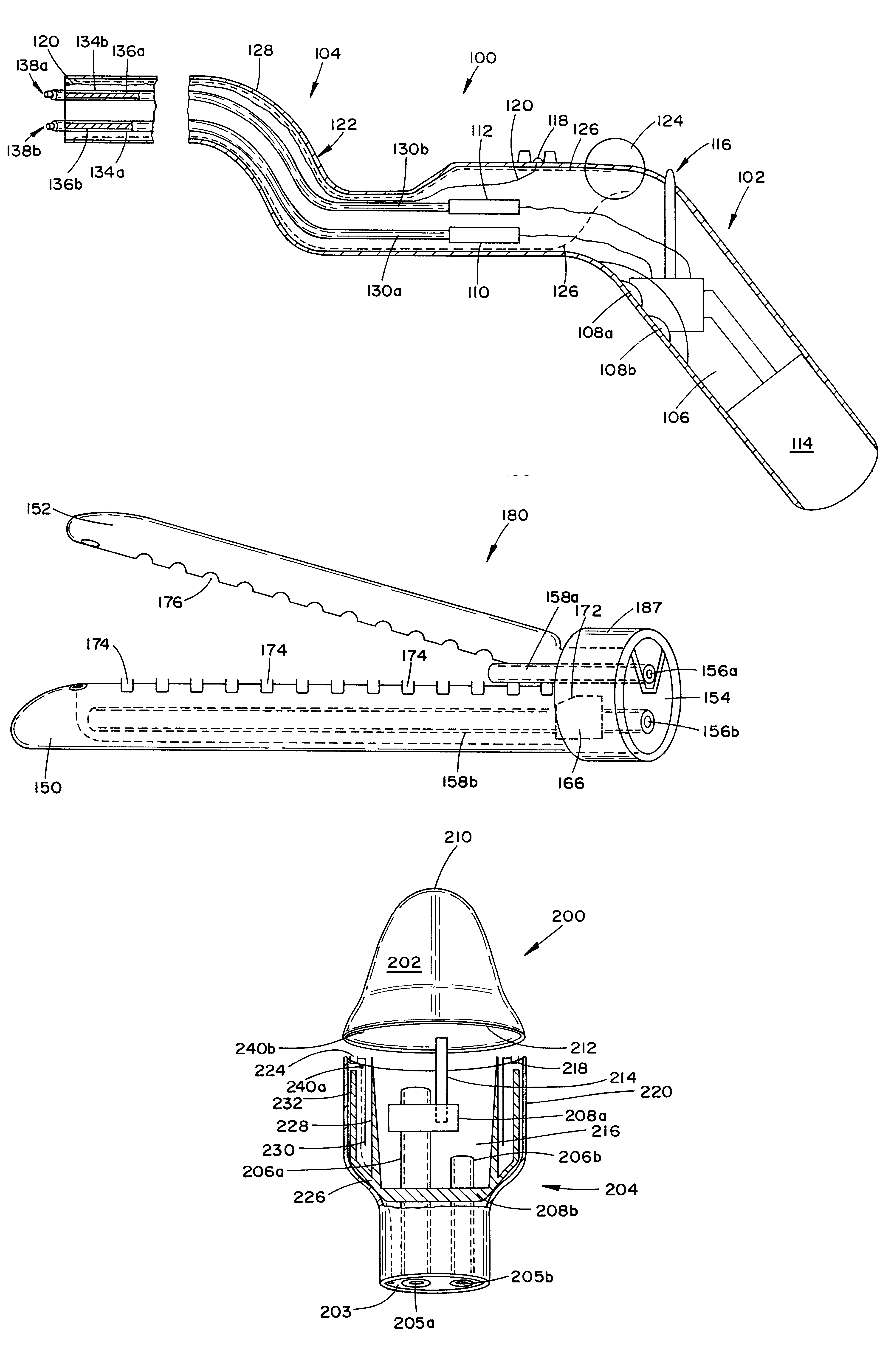
More particularly, with respect to the motors 110,112, each is a dual direction motor. In addition to being coupled to the finger actuateable switch, the motors are also each separately coupled to a power source 114 (which is a common source in the present embodiment) and a manual drive switch 116. The manual drive switch 11...


PUM

PropertyMeasurementUnit
flexibleaaaaaaaaaa
torqueaaaaaaaaaa
poweraaaaaaaaaa

Abstract

An electromechanical driver for use in gastrointestinal tract surgery, including a flexible sheath and a handle, is provided. Also dislosed are a series of surgical attachments which may be utilized in conjunction with the electromechanical driver. The handle of the driver includes at least one motor which is selectively engageable by the actuation of a trigger. The motor is coupled to a flexible drive shaft which extends through the flexible sheath. At a distal end of the flexible sheath, and correspondingly at the end of the drive shaft, the various surgical attachments may be coupled. The turning of the drive shaft provides the necessary power to actuate the surgical instrument.

Description

1. Field of the InventionThe present invention relates generally to an electromechanical device for use with anastomosing, stapling, and resecting surgical tools, and more specifically to a electromechanical device by which surgical instruments such as anatomosing, stapling, and resecting tools may be remotely actuated.2. Description of the Prior ArtUpon identification of cancerous or other anomalous tissue in the gastrointestinal tract, surgical intervention is often prescribed. The field of cancer surgery, and more specifically, the surgical procedure by which a section of the gastrointestinal tract which includes cancerous or anomalous tissue is resected, includes a number of uniquely designed instruments. In combination with a description of the present instrumentation and their functions, a description of the state of the art in this surgical procedure shall also be provided.The first question which must be answered when determining how to treat gastrointestinal cancer relates ...

Claims


Application Information

Patent Timeline
Patent Type & Authority Patents(United States)
IPC IPC(8): A61B17/11A61B17/068A61B17/03A61B17/072A61B17/28A61B17/00
CPCA61B17/07207A61B17/1114A61B17/1155A61B2017/00039A61B2017/003A61B2017/00323A61B2017/00398A61B2017/00464A61B2017/00473A61B2017/07214A61B2017/07278A61B2017/2905
Inventor WHITMAN, MICHAEL P.
Owner DORROS GERALD M D
Why Eureka
Try Eureka