Linear measuring machine

a linear measuring machine and measuring device technology, applied in the direction of mechanical measuring devices, mechanical measuring arrangements, instruments, etc., can solve the problems of workpiece scarring or probe damag

Inactive Publication Date: 2002-09-10
MITUTOYO CORP
View PDF5 Cites 36 Cited by
  • Summary
  • Abstract
  • Description
  • Claims
  • Application Information

AI Technical Summary

Benefits of technology

In the above arrangement, the controller lifts or lowers the slider by driving the elevation driving mechanism when a measurement command is given. When the controller detects that the probe touches the measurement surface of the workpiece by lifting or lowering the slider, the controller drives the elevation driving mechanism in a direction for the probe to move away from the measurement surface of the workpiece after the detection value of the displacement sensor at that time is fetched. Accordingly, since the workpiece and the probe are separated in the above condition, the workpiece is not scarred or the probe is not damaged even when the measuring machine and / or the workpiece are moved immediately after the measurement. Accordingly, the measuring machine and the workpiece are not damaged and measurement efficiency can be improved.
Accordingly, since the slider is forcibly stopped after the predetermined time even when the probe keeps on retracting beyond the retraction target position, the probe and the workpiece are less likely to interfere with each other.
Accordingly, since the retraction amount can be set at will in accordance with the portion of the workpiece to be measured, the interference between the probe and the workpiece can be prevented.
Accordingly, since the elevation driving mechanism is stopped when the probe is retracted to the measurement initiation position if the retraction amount is larger than a distance for the probe to touch the measurement surface of the workpiece from the measurement initiation position, the interference between the probe and the workpiece can be prevented in advance.
According to the above arrangement, since the brake is actuated before the retraction target position after the retraction of the slider, the slider can be stopped at an early stage and the interference between the probe and the workpiece can be prevented in advance.

Problems solved by technology

If the measuring machine and / or the workpiece are moved immediately after measurement without the above operation, since the workpiece and the probe moves while keeping interference therebetween, i.e. the workpiece and the probe are in contact with each other during movement, the workpiece can be scarred or the probe may be damaged.

Method used


Image

  • Linear measuring machine
  • Linear measuring machine
  • Linear measuring machine

Examples


Embodiment Construction

)

An embodiment of the present invention will be described below with reference to attached drawings.

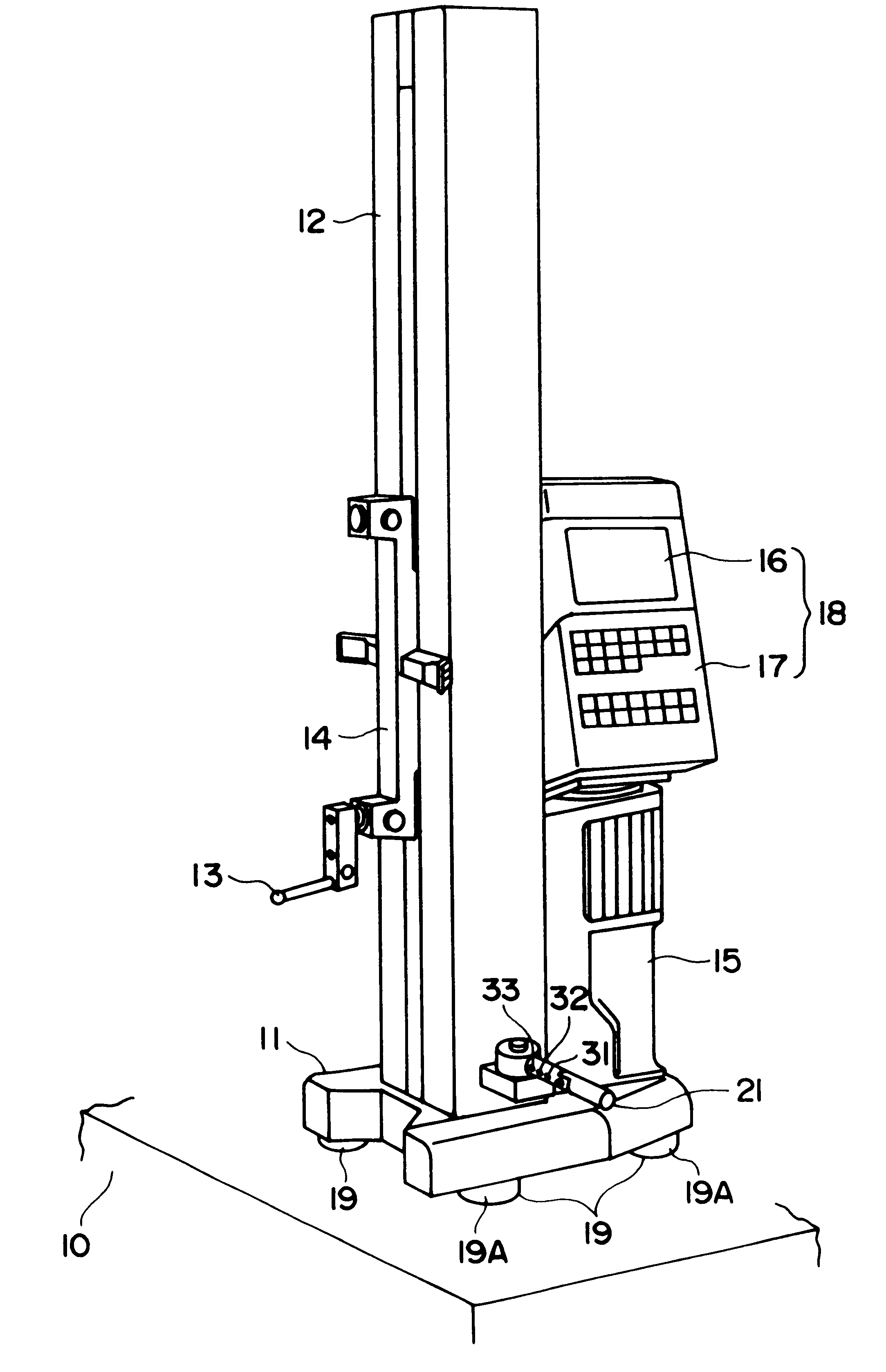
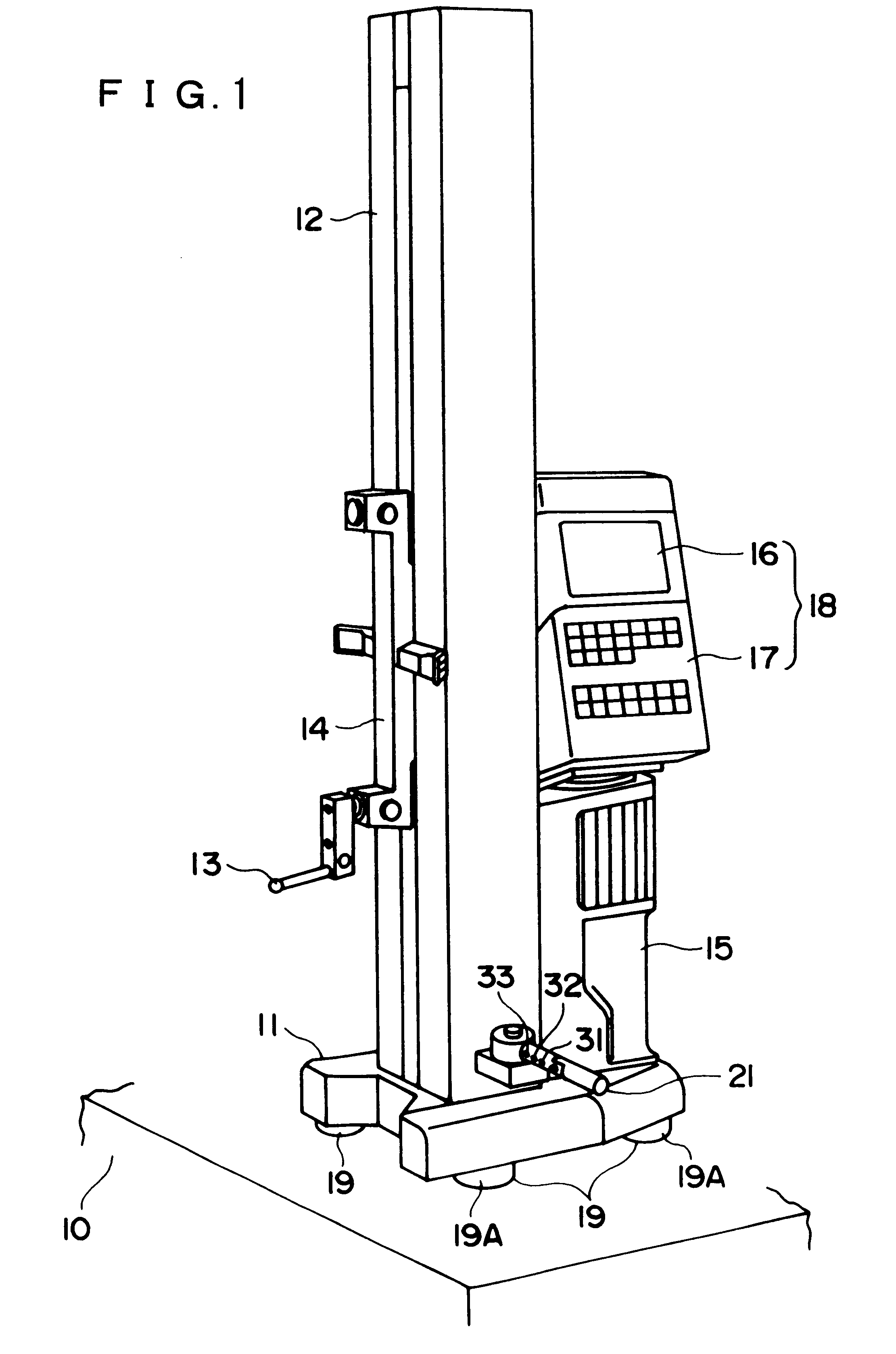
FIG. 1 is a perspective view of a height gauge as a linear measuring equipment of the present embodiment. As shown in the figure, the height gauge according to the present embodiment includes a base 11 movably disposed on a surface plate 10, a column 12 vertically disposed on the base 11, a slider 14 vertically elevatable along the column 12 and having a probe 13.

A grip portion 15 is provided to the base 11 opposite to the column 12, and a display console 18 is provided to an upside of the grip portion 15 that has a display 16 such as LCD and a key input portion 17 on a surface thereof.

An air-flotation mechanism 19 for blowing out air from the base 11 to the surface plate 10 to float the base 11 relative to the surface plate 10 is provided on a lower side of the base 11. The air-flotation mechanism 19 includes a plurality of air pads 19A provided to a lower side of the base 11 and hav...


PUM


Abstract

A linear measuring machine is provided, the linear measuring machine having a base (11), a column (12) disposed on the base, a slider (14) elevatable along the column and an elevation driving mechanism (44) including a motor for lifting and lowering the slider. The linear measuring machine further includes a touch-and-back mechanism for driving the elevation driving mechanism in a direction for a probe (13) to move away from a measurement surface of the workpiece after fetching a detection value of a displacement sensor (45) when the probe touches the measurement surface of the workpiece and for stopping the elevation driving mechanism.

Description

1. Field of the InventionThe present invention relates to a linear measuring machine having a vertically elevatable probe to touch a target portion of a workpiece to measure a dimension of the workpiece such as height, step, hole and shaft.2. Description of Related ArtFor measuring a dimension of a workpiece such as height, step, hole and shaft is measured on a surface plate, a linear measuring machine having a vertically elevatable probe, so-called height gauge is used.Among the height gauge, a motor-driven type height gauge has a base movable disposed on a surface plate, a column standing on the base, a slider elevatable along the column and having a probe, an elevation driving mechanism including a motor for elevating the slider, a displacement sensor for detecting a displacement amount of the slider in height direction, a display, and a controller for elevating the slider by driving the elevation driving mechanism based on a measurement command, for fetching a detection value of...

Claims


Application Information

Patent Timeline
Patent Type & Authority Patents(United States)
IPC IPC(8): G01B5/02G01B7/004G01B5/06G01B5/00G01B21/02H02K41/02
CPCG01B5/061G01B7/004G01B7/082G01B7/102
Inventor ZHANG, YUWUYAMAGATA, MASAOKITOKITO, HIROYUKINOMURA, YOICHIAOYAMA, BUNJI
Owner MITUTOYO CORP
Why Eureka
Try Eureka