
Friction feed wheel mechanism with vibration excitation

a friction feed wheel and vibration excitation technology, which is applied in the direction of knitting, thin material processing, papermaking, etc., can solve the problems of friction-controlled switch-off, damage to threads and/or friction linings, and inability to properly operate, so as to improve the removal properties, improve the effect of thread removal, and good thread feeding

Inactive Publication Date: 2002-09-10
MEMMINGER IRO GMBH
View PDF7 Cites 3 Cited by
  • Summary
  • Abstract
  • Description
  • Claims
  • Application Information

AI Technical Summary

Benefits of technology

In this way the detachment of the thread from the contact surface of the thread feed wheel is made considerably more easy, in particular in case of a feed stop, and the remaining contact between the thread and the thread feed wheel is minimized.
If the thread adheres to the contact surface, it is possible to overcome the static friction by means of the vibration applied to the thread, the thread guide element, the thread feed wheel or the thread guide lever or other element, which considerably improves the removal properties (switching the thread feed off). This applies in particular, but not exclusively, to thread feed wheels having a coating with a large coefficient of friction or a structured surface, which permits good thread feeding. Moreover, this applies in particular to threads having a large coefficient of friction. A further advantage lies in that deposited dirt, which possibly can lead to adherence, such as sizing, oil or the like, does not lead, or leads less, to adherence of the thread. The step of exposing the contact between the thread and the thread feed wheel to a certain vibration, therefore drastically improves the thread removal, i.e. the disruption of the thread feed wheel which takes the thread along.
Because of the application of vibration to the thread it is possible for the latter to be lifted off the thread feed wheel almost completely when the thread is standing still, wherein at most a small area of contact between the thread and the thread feed wheel remains, in which the thread then rests against the thread feed wheel without or under only little tension. Because of this, long thread idle times are possible without damage to the thread or to the thread feed wheel.
A particularly operator-friendly structure results if both the inlet thread guide element, placed upstream of the thread feed wheel, and the outlet thread guide element, placed downstream of the thread feed wheel, are arranged to be accessible from the direction of the operating side of the thread feed device, and if both the thread guide element of the thread guide lever and the thread travel path on the thread feed wheel are fixed on a section of the circumference of the thread feed wheel which faces the operating side. Therefore the thread need not be conducted behind the thread feed device in the course of being threaded, which makes the operation considerably easier.

Problems solved by technology

The result of this can be that the friction-controlled switch-off, i.e. the stoppage of feeding by the friction feed wheel mechanism, does not take place correctly.
Even if the thread is detached from the friction lining, damage of the thread and / or of the friction lining can occur because of the remaining contact between the thread and the thread lining of the rotating drum during extended periods of stoppage of the thread.
Rubber linings are particularly endangered.
Too low a coefficient of friction, however, can interfere with the reaction properties of the friction feed wheel mechanism, if a thread feed suddenly occurs and thread must again be fed in following a feeding stop.

Method used


Image

  • Friction feed wheel mechanism with vibration excitation
  • Friction feed wheel mechanism with vibration excitation
  • Friction feed wheel mechanism with vibration excitation

Examples


Embodiment Construction

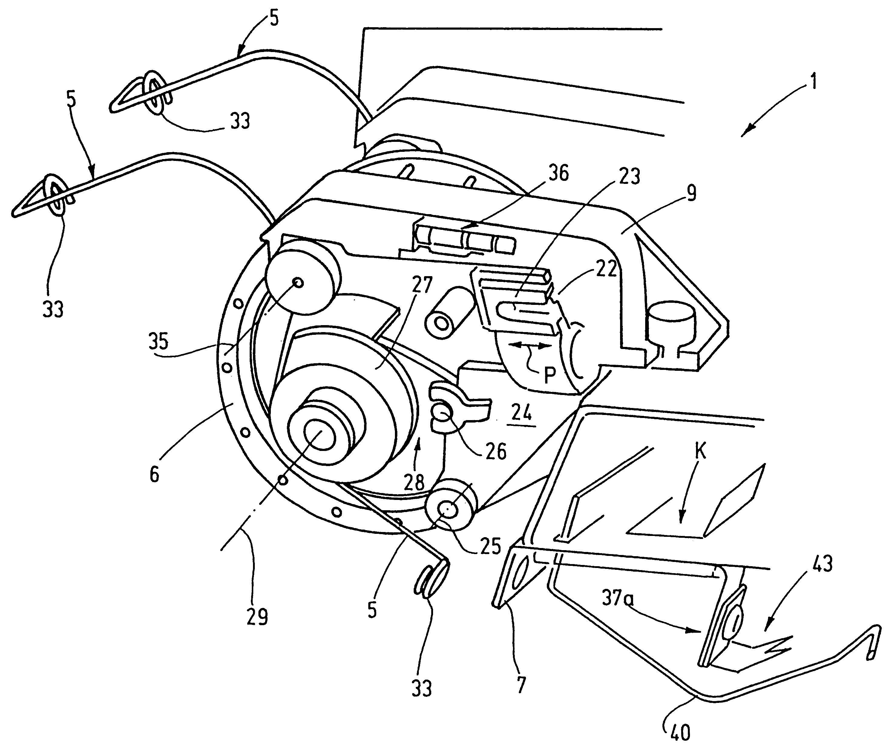
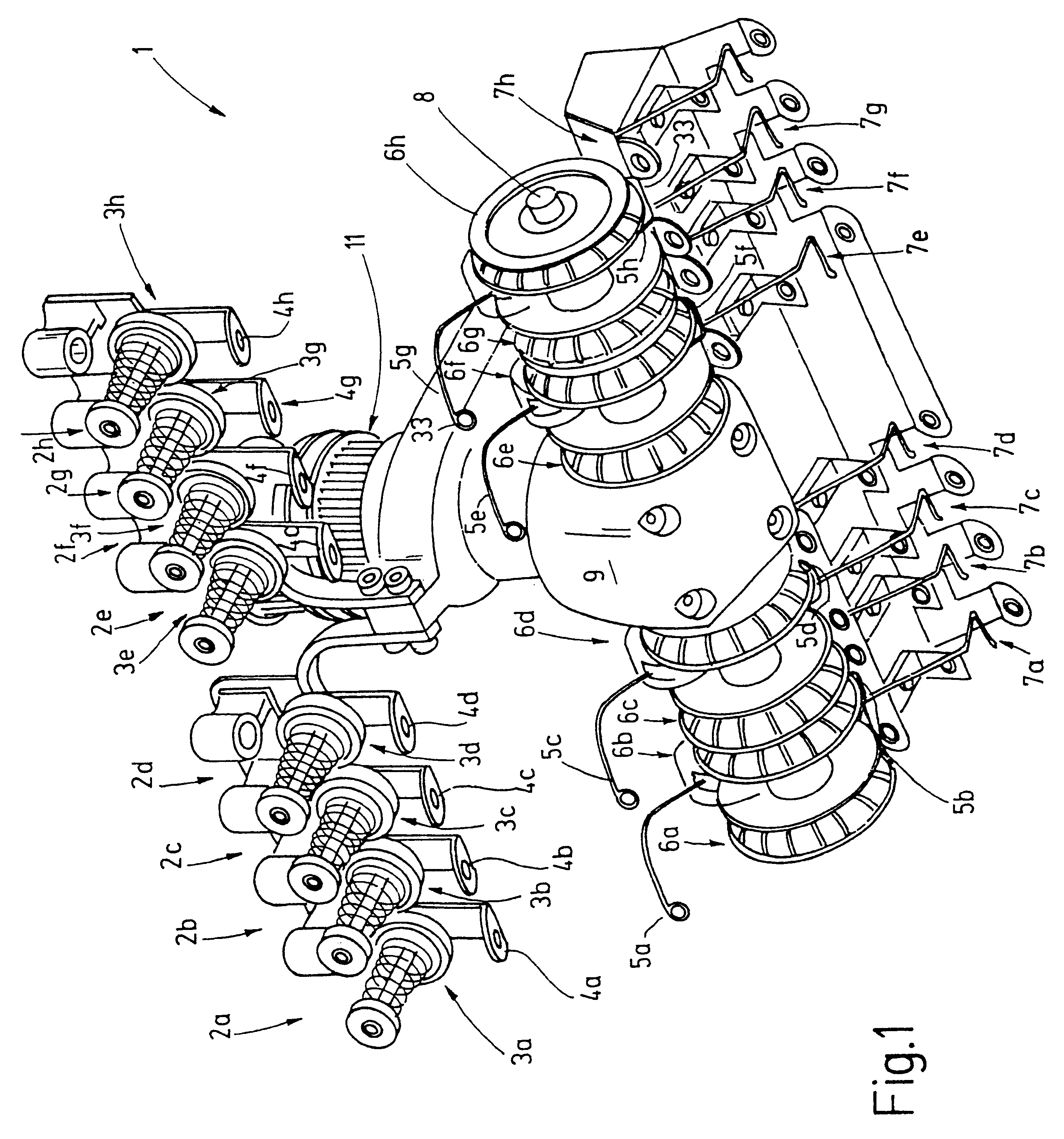
A vibration feed wheel mechanism 1 is represented in FIG. 1, which has a total of eight thread feed tracks and therefore eight thread feed systems 2a to 2h, which are basically designed identical, and each of which has a thread brake 3, 3a-3b a thread guide eye 4, 4a-4h, a thread guide lever 5, 5a-5h, a thread feed wheel 6, 6a-6h, and thread guides eyes 7, 7a-7h on the outlet side. To distinguish them, the respective elements are identified by letter indices in FIG. 1.

The thread feed wheels 6a to 6h are supported on a common shaft 8, with which they are connected, fixed against relative rotation. The shaft 8 is rotatably seated by means of a bearing device, not shown in detail, held in a housing 9, and constitutes a support device for the thread feed wheel 6. In addition, the housing 9 contains an angular gear, whose power take-off side is the shaft 8, and whose input shaft supports pulleys 11 for driving the thread feed wheels 6a to 6h.

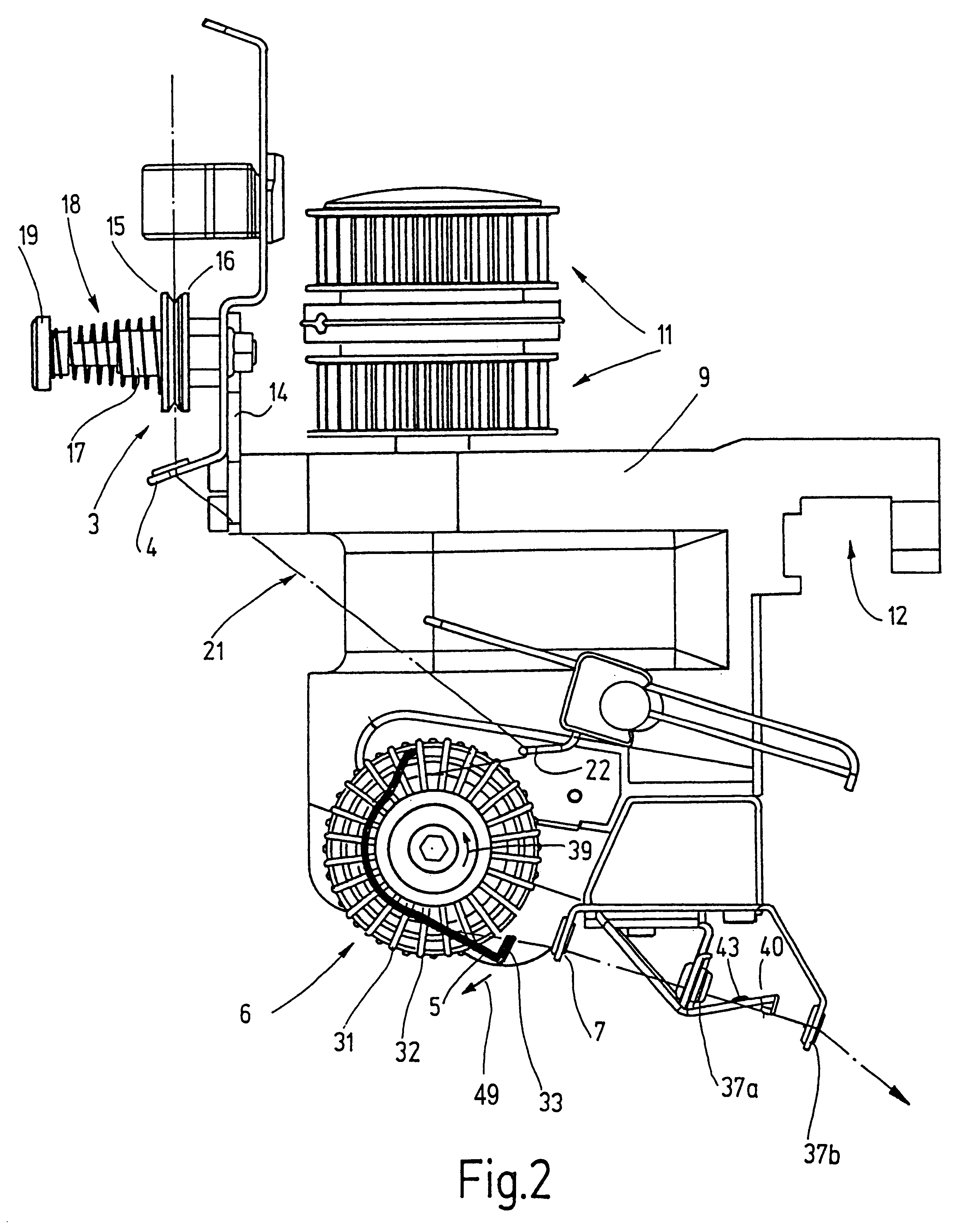
As FIG. 2 shows, the housing 9 is provided on ...


PUM


Abstract

A vibration friction feed wheel mechanism for feeding thread to a thread processing machine having intermittent thread requirement. The feed wheel mechanism including a high friction contact surface, a thread guide level for lifting thread off of the feed wheel and a vibration generating arrangement for applying a vibrational movement to the thread. The vibration of the thread ensures that the thread lifts-off from the contact surface of the friction feed wheel by reducing the coefficient of friction between the thread and the high friction contact surface of the friction wheel.

Description

The invention relates to a friction feed wheel mechanism with vibration excitation.So-called friction feed wheel mechanisms are often employed for feeding thread to thread-processing machines, in particular those, which have a chronologically fluctuating or intermittent thread requirement. These have a thread feed wheel, which is driven at a constant number of revolutions and has a contact surface for the thread. The thread is wrapped around the thread feed wheel at a wrap angle which is mostly less than 360.degree.. The thread is moreover conducted through the eye of a thread guide lever, wherein the position of the lever affects the wrap angle. The thread guide lever is usually pre-stressed away from the thread feed wheel by means of a spring force. When the use of thread by the thread-processing machine ends, the thread guide lever slightly lifts the thread off the thread feed wheel or reduces the wrap angle, so that the thread feeding is stopped. Thus, the thread usage controls ...

Claims


Application Information

Patent Timeline
IPC IPC(8): D04B15/38D04B15/48B65H51/06B65H54/42B65H59/10B65H51/22B65H59/14
CPCD04B15/48B65H51/06B65H57/06
Inventor SCHMODDE, HERMANNWORNER, CHRISTOPH
Owner MEMMINGER IRO GMBH
Learn More