

High-pressure integral tube coupling arrangements
a technology of integral tubes and coupling arrangements, applied in the direction of hose connections, braking systems, braking components, etc., can solve the problem of increasing the number of potential leakage paths
- Summary
- Abstract
- Description
- Claims
- Application Information
AI Technical Summary
Problems solved by technology
Method used
Image

Examples
first embodiment
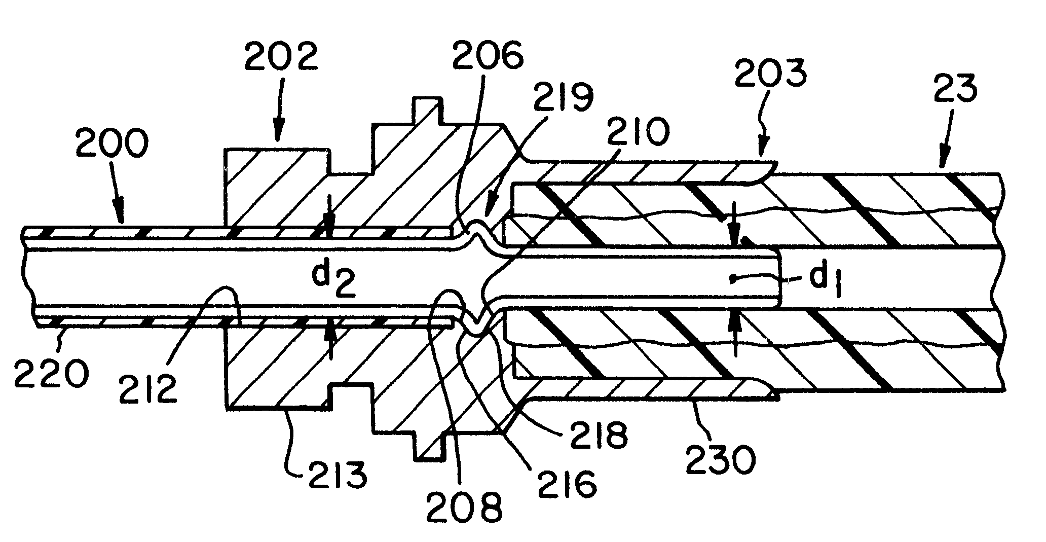
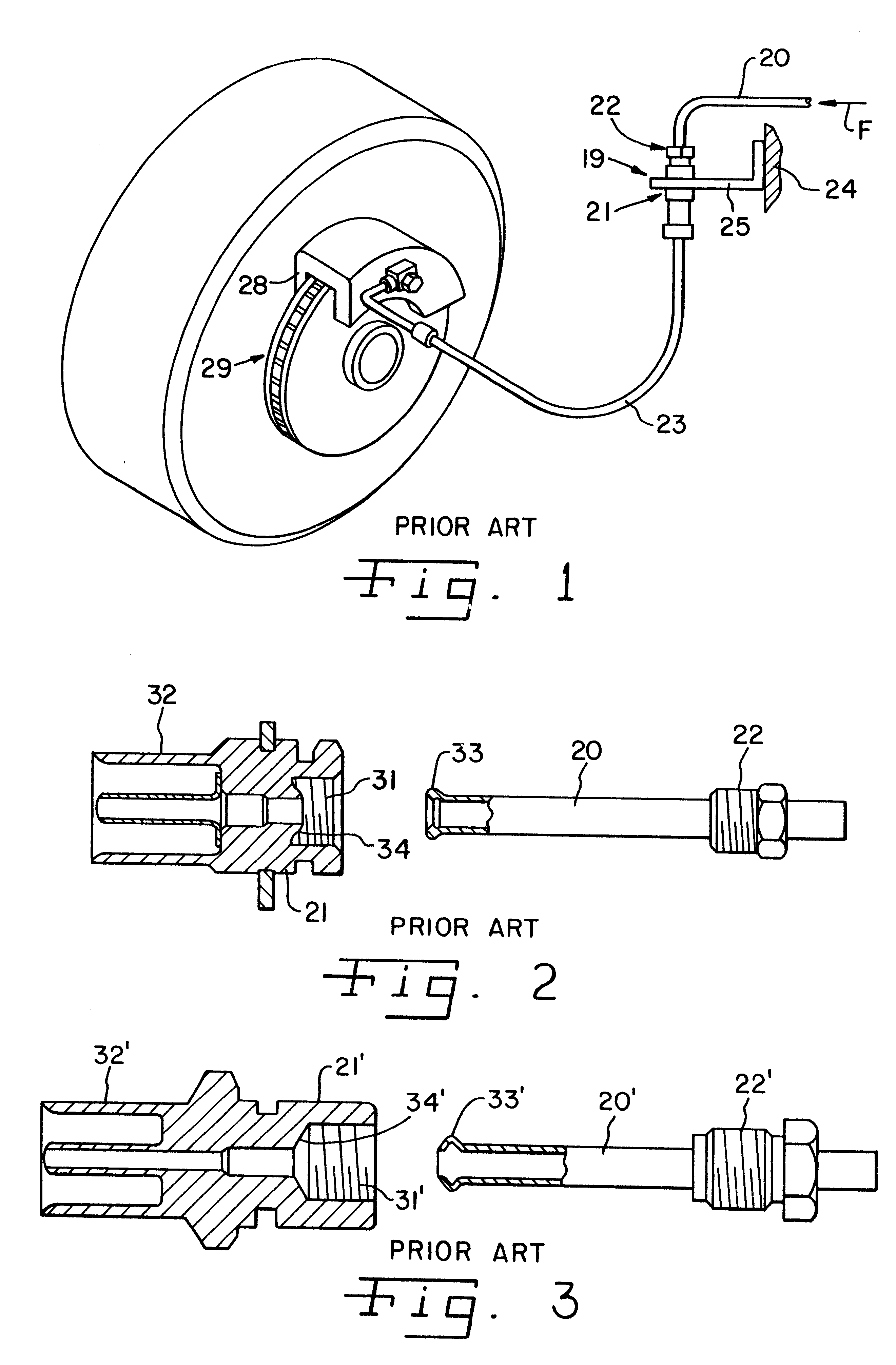
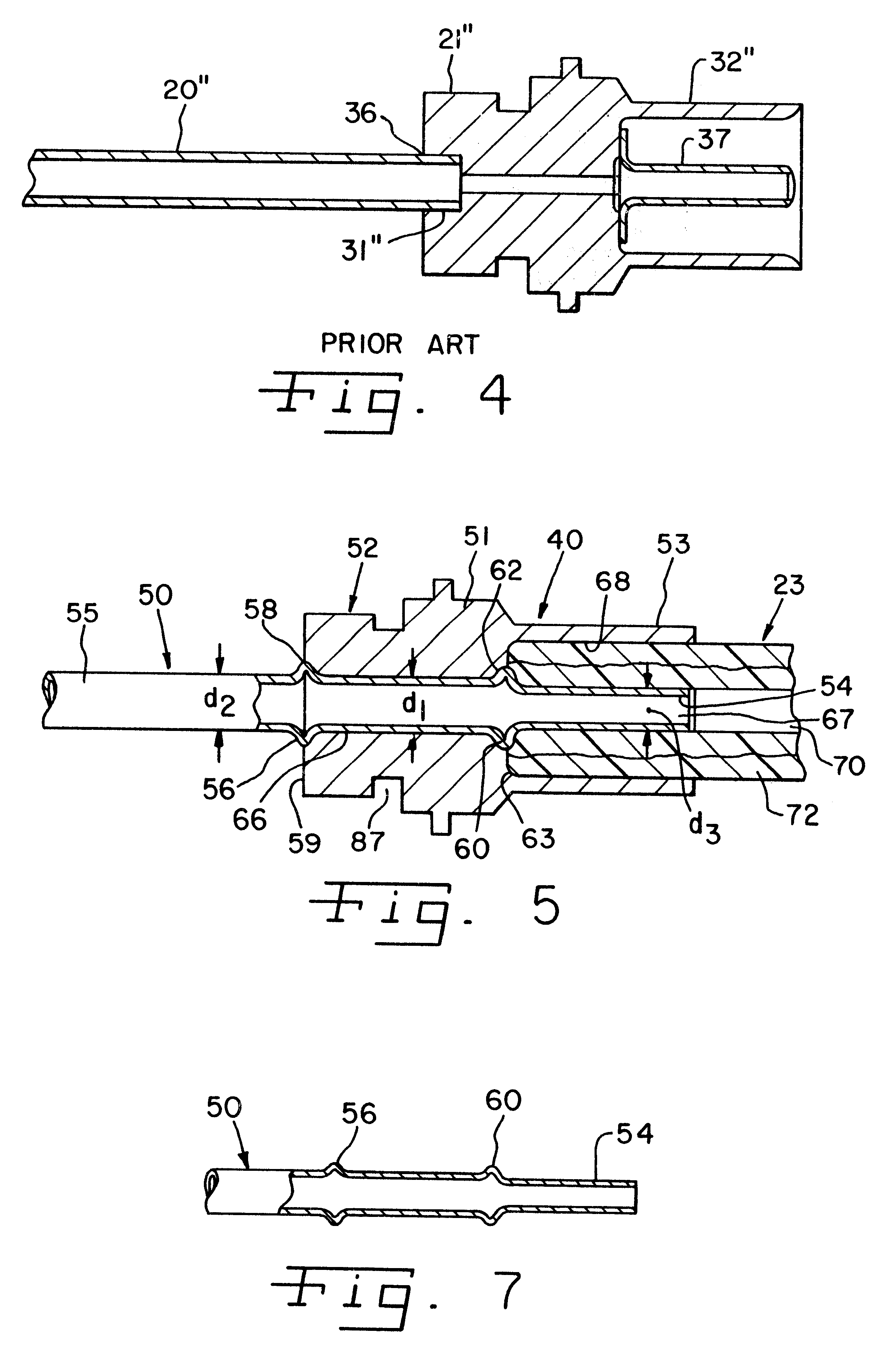
Referring now to the present invention illustrated in FIGS. 5-9, a high pressure integral tube coupling 40 enables a direct connection between a metal tube 50 and a flexible hose 23 (see FIG. 1), such as a high pressure resistant rubber hose, without a need for rotating threaded coupling components or brazing, thus eliminating parts or steps while retaining their function. As is seen in FIG. 5, the metal tube 50 is positioned within a body portion 51 of a fitting 52 to which the hose 23 of FIG. 1 is subsequently coupled by deforming a crimping collar 53 therearound so that the hose is axially retained within the fitting 52 and is radially sealed against an end portion 54 of the tube. The tube 50 corresponds to the tubes 20 shown in the prior art arrangements of FIGS. 1-4 and has an internal diameter of about 0.1250 inch, which internal diameter could range from about 0.125 to about 0.145 inch.
In order to retain the tube 50 in the fitting 52, a back bead 56 is preferably seated withi...
third embodiment
Preferably, the metal tube 50 is made of steel and is pre-coated by SAE-J527 Standards, sliding fit. Other materials which may be used are copper, nickel, NYLON.RTM. (polyamide) or polyvinyl fluoride. If relatively thick plastic coatings such as NYLON.RTM. are used, the coating preferably terminates before the first bead 56; however, as is seen in FIGS. 10 and 11, can continue to bead 60. The barbed or stem structure beyond the beads 56 and 60 has a controlled inside diameter as well as a controlled outside diameter which permits the assembly to pass the Federal Motor Vehicle Safety Standards for minimum fluid passage diameter. Moreover, the barb or stem structure can be produced either with or without annular grooves to increase tensile integrity of the coupling. Since the end 54 of the tube is received directly within the bore 70 of the hose 23, potential leak paths which occur with additional elements, such as those in prior art threaded connections and brazed tubular supports, a...
second embodiment
Referring now to FIG. 9, there is shown the invention, wherein the bead pockets 58 and 62 are deleted from the fitting 52' so that beads 56' and 60' press directly against the radially extending back and front end surfaces 80 and 82, respectively of the fitting 52'. Friction between the end surface 80 and back bead 56 and between the front end surface 82 and the front bead 60 prevents rotation of the tube 50 within the fitting. In addition, there is a slight friction fit between the tube 50 and the bore 66' which provides a fluid seal.
Referring now to FIG. 10, there is shown a third embodiment of the invention wherein a tube 90 is inserted into a fitting 92 having a crimping collar 93. The tube 90 has a necked down portion 94 joined thereto by a frusto-conical section or tapered 95. The frusto-conical section 95 joins an intermediate section 96 just in front of a bead 97. The fitting 92 has a smooth bore 100 that has an abutment surface 101 defined by an annular shoulder 102 therein...
PUM
| Property | Measurement | Unit |
|---|---|---|
| internal diameter | aaaaa | aaaaa |
| internal diameter | aaaaa | aaaaa |
| thick | aaaaa | aaaaa |
Abstract
Description
Claims
Application Information