Liquid ejecting method, liquid ejecting head, head cartridge and liquid ejecting apparatus using same
a liquid ejecting and liquid ejecting technology, applied in printing and other directions, can solve the problems of deteriorating energy use efficiency and ejection force, large amount of deposition, and unstable ink ejection
- Summary
- Abstract
- Description
- Claims
- Application Information
AI Technical Summary
Benefits of technology
Problems solved by technology
Method used
Image
Examples
example 3
of Head
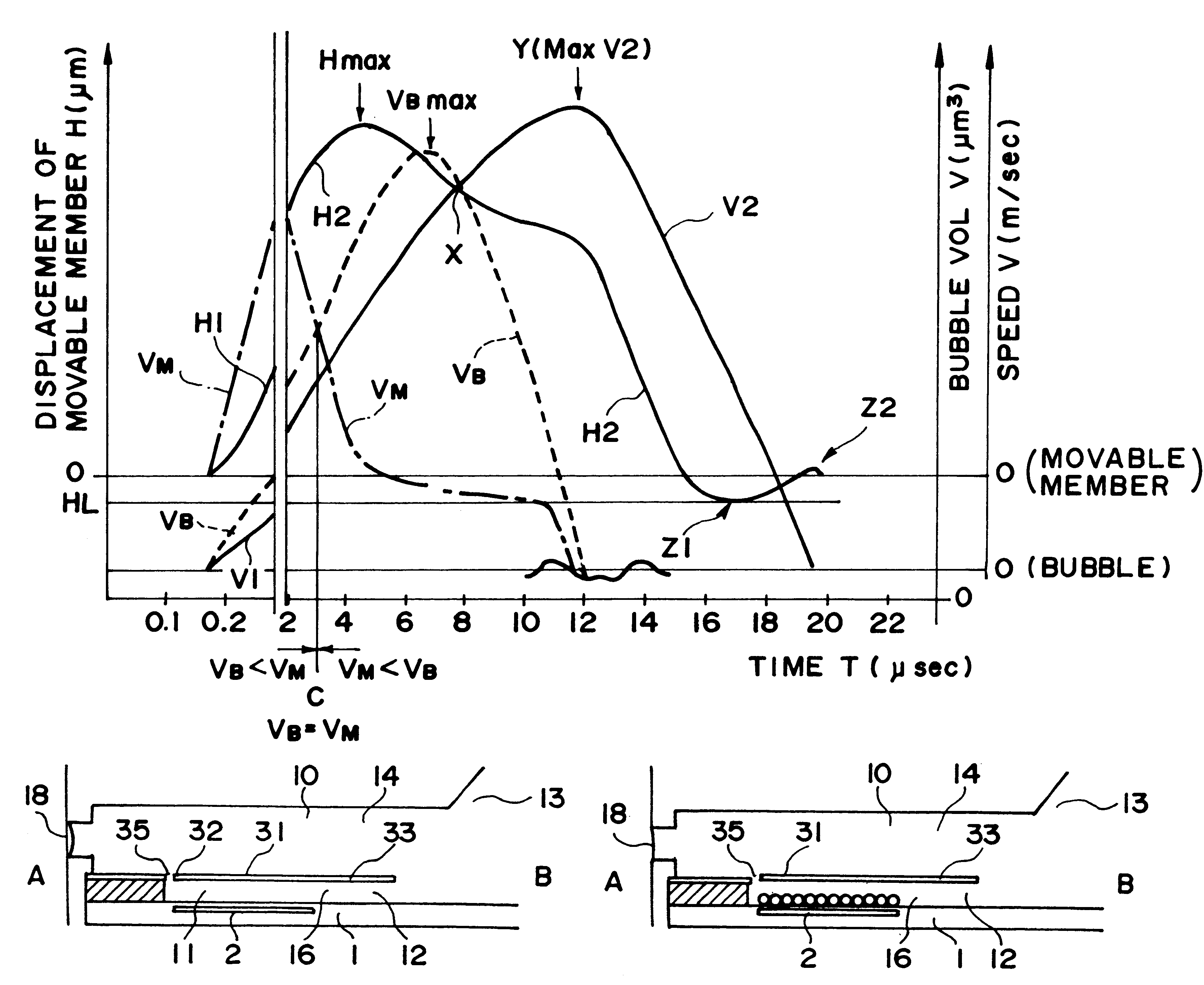
FIG. 10 shows example 3, wherein the positional relation is shown among the bubble generating region in the liquid flow path, the bubble and the movable member 31.
In most of the foregoing examples, the pressure of the bubble generated is concentrated toward the free end of the movable member 31, by which the movement of the bubble is concentrated to the ejection side 18, simultaneously with the quick motion of the movable member 31. In this embodiment, a latitude is given to the generated bubble, and the downstream portion of the bubble (at the ejection outlet 18 side of the bubble) which is directly influential to the droplet ejection, is regulated by the free end side of the movable member 31.
As compared with FIG. 2 (first embodiment), the head of FIG. 10 does not include a projection (hatched portion) as a barrier at a downstream end of the bubble generating region on the element substrate 1 of FIG. 5. In other words, the free end region and the opposite lateral end region...
example 4
of Head
In this embodiment, the ejection power for the liquid by the mechanical displacement is further enhanced. FIG. 11 is a cross-sectional view of such a head structure. In FIG. 11, the movable member is extended such that position of the free end of the movable member 31 is positioned further downstream of the ejection outlet side end of the heat generating element. By this, the displacing speed of the movable member at the free end position can be increased, and therefore, the production of the ejection power by the displacement of the movable member is further improved.
In addition, the free end 32 is closer to the ejection outlet side than in the foregoing example, and therefore, the growth of the bubble can be concentrated toward the stabilized direction, thus assuring the better ejection.
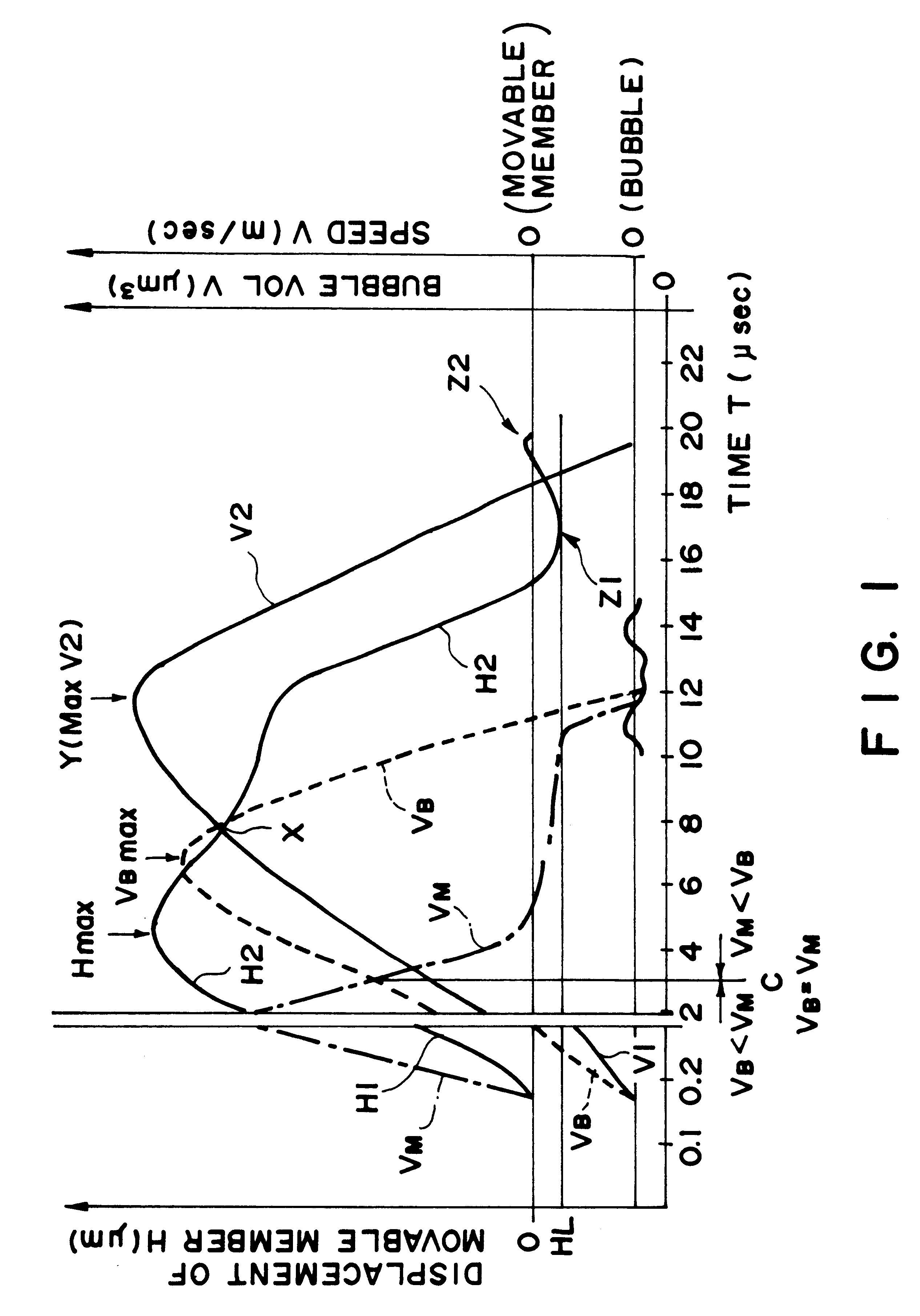
The movable member 31 returns from the second position (max displacement) by its resiliency at a returning speed R1, wherein the free end 32 which is remote from the fulcrum 33 returns at a ...
example 5
of Head
FIGS. 12, (a), (b), (c) shows Example 5. As is different from the foregoing embodiment, the region in direct communication with the ejection outlet is not in communication with the liquid chamber side, by which the structure is simplified.
The liquid is supplied only from the liquid supply passage 12 along the surface of the bubble generation region side of the movable member 31. The free end 32 of the movable member 31, the positional relation of the fulcrum 33 relative to the ejection outlet 18 and the structure of facing to the heat generating element 2 are similar to the above-described embodiment. According to this embodiment, the advantageous effects in the ejection efficiency, the liquid supply performance and so on described above, are accomplished. Particularly, the retraction of the meniscus is suppressed, and a forced refilling is effected substantially thoroughly using the pressure upon the collapse of bubble. FIG. 12, (a) shows a state in which the bubble generati...
PUM
 Abstract
Description
Claims
Application Information
 - R&D
- Intellectual Property
- Life Sciences
- Materials
- Tech Scout
- Unparalleled Data Quality
- Higher Quality Content
- 60% Fewer Hallucinations
Browse by: Latest US Patents, China's latest patents, Technical Efficacy Thesaurus, Application Domain, Technology Topic, Popular Technical Reports.
© 2025 PatSnap. All rights reserved.Legal|Privacy policy|Modern Slavery Act Transparency Statement|Sitemap|About US| Contact US: help@patsnap.com


