Transmission vent assembly

a technology of transmission vents and assembly parts, which is applied in the direction of gearing details, filtration separation, separation processes, etc., can solve the problems of reducing the volume of fluid inside the transmission, affecting the efficiency of the transmission, so as to achieve the effect of reducing water ingestion

Inactive Publication Date: 2002-09-10
ALLISON TRANSMISSION INC
View PDF8 Cites 86 Cited by
  • Summary
  • Abstract
  • Description
  • Claims
  • Application Information

AI Technical Summary

Benefits of technology

Two bi-directional air flow paths extend between the transmission and the atmosphere through the internal passage, the connecting air passage, the annular air cavity, and each of the two thre

Problems solved by technology

Without a vent for breathing, the increased internal pressure relative to the atmospheric exterior pressure may force fluid past the housing seals.
Without the vent, contaminants such

Method used


Image

  • Transmission vent assembly
  • Transmission vent assembly
  • Transmission vent assembly

Examples


Embodiment Construction

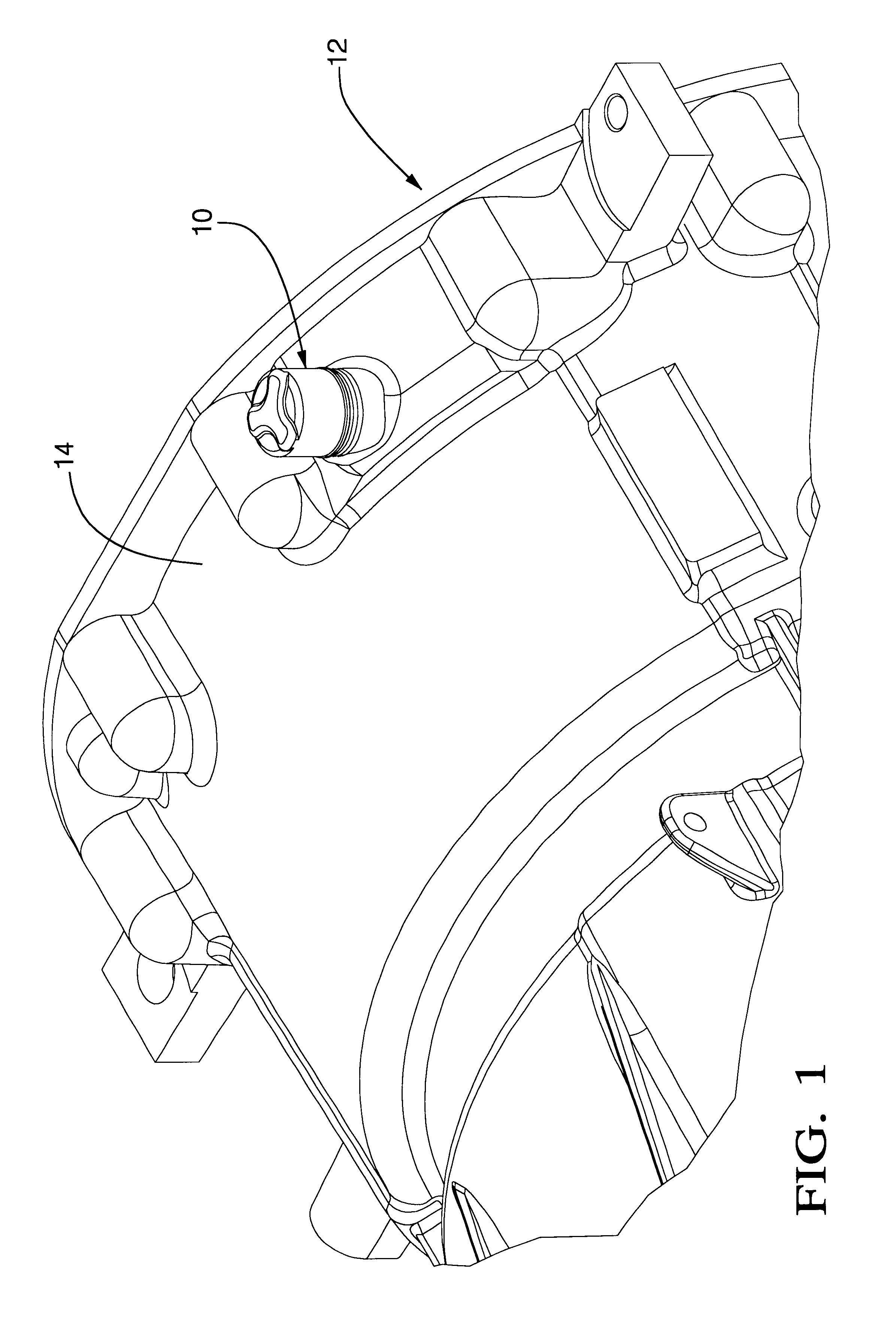
The present invention transmission vent assembly 10 is incorporated in a transmission 12, a portion of which is shown in FIG. 1. The vent assembly 10 is installed in an upper surface of a transmission housing 14 in a generally vertical orientation.

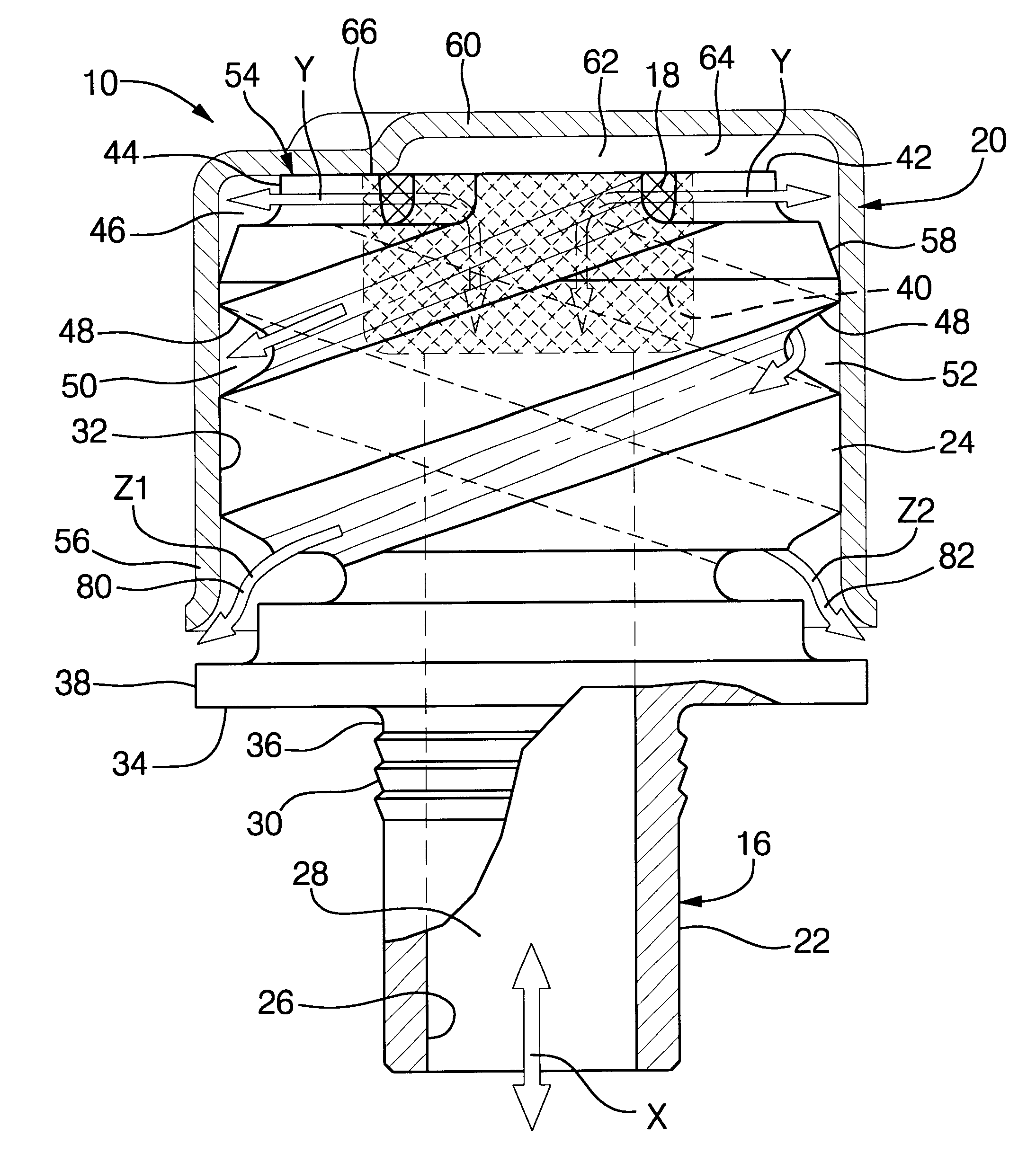
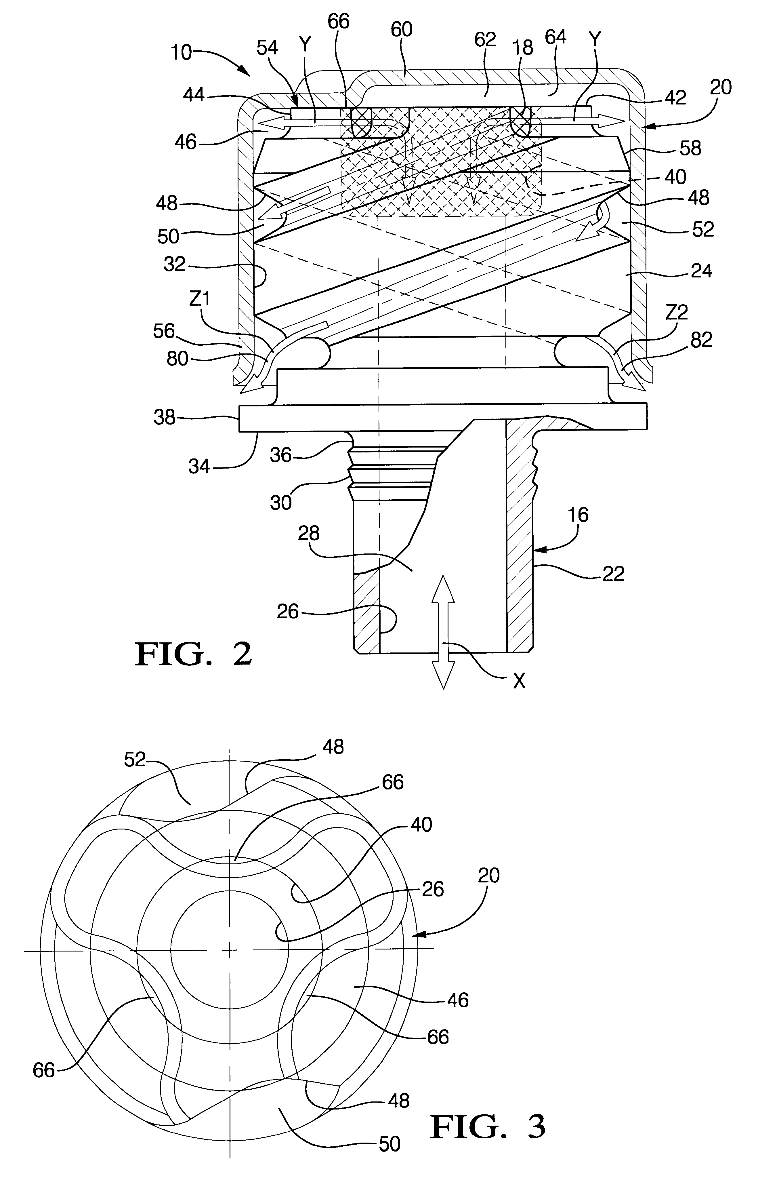
Referring now to FIG. 2, a cross sectional view of the vent assembly 10 is illustrated. The vent assembly 10 includes three main components: a vent apparatus 16, a filter 18 fitted in the vent apparatus 16, and a cap 20 snapped over the vent apparatus. The vent apparatus 16 is comprised of a cylindrical tube portion 22 and a vent body portion 24. A central bore 26 defining an internal passage 28 extends through the length of the vent apparatus 16. The cylindrical tube portion 22 is received in a mounting hole, not shown, in the transmission housing 14. It is preferable for the vent assembly 10 to be press fittingly received in the mounting hole, with serrations 30 about the tube portion 22 to aid retention, as opposed to a threaded connect...


PUM

PropertyMeasurementUnit
Pressureaaaaaaaaaa
Diameteraaaaaaaaaa

Abstract

A transmission vent assembly includes an apparatus having a central, internal passage extending therethrough. The internal passage has a larger diameter portion defining a pocket. A filter is disposed in the pocket to condense and return fluid to the transmission through the internal passage. The apparatus includes a shoulder adjacent the upper surface and a double lead thread initiating at the shoulder and terminating at a lower end. The assembly further includes a cup-shaped cap, press fittingly disposed over the apparatus. The cap and shoulder define an annular cavity and the cap and the double lead thread define first and second threaded passages. The cap includes an outward impression in the closed end which cooperates with the upper surface of the apparatus to define a connecting passage. Two bi-directional air flow paths extend between the transmission and the atmosphere through the internal passage, connecting air passage, annular air cavity, and each of the two threaded passages.

Description

TECHNICAL FIELDThe present invention relates to a transmission vent assembly to venting a vehicular transmission.BACKGROUND OF THE INVENTIONIn conventional vehicular transmissions, an air vent assembly is provided to allow air to flow into and out of the transmission housing during operation, referred to as transmission breathing. As heat is generated in the transmission, the temperature of the air and hydraulic fluid therein increases, and likewise the internal pressure increases. Without a vent for breathing, the increased internal pressure relative to the atmospheric exterior pressure may force fluid past the housing seals. When the internal temperature decreases relative to the exterior temperature, such as when a vehicle is driven through high water, the pressure differential is reversed and air flows into the transmission through the vent. Without the vent, contaminants such as dirt and water may be drawn into the transmission through the seals.Thus a vent or breather is typic...

Claims


Application Information

Patent Timeline
IPC IPC(8): F16H57/02F16H57/027
CPCF16H57/027Y10T74/2186
Inventor RASZKOWSKI, JAMES ALLENROCKEY, CONRAD L.
Owner ALLISON TRANSMISSION INC
Why Eureka
Try Eureka