
System for graphically generating logic for a cause and effects matrix

Inactive Publication Date: 2002-09-10
SIEMENS ENERGY & AUTOMATION INC
View PDF2 Cites 58 Cited by
  • Summary
  • Abstract
  • Description
  • Claims
  • Application Information

AI Technical Summary

Benefits of technology

The present invention provides a system and method

Problems solved by technology

When using programmable logic controllers (PLCs), for example, this typically means the arduous labor intensive job of implementing some type of logic, for example ladder logic or Boolean function block diagrams.
It is not uncommon for various errors to arise during the development of the logic for the Cause and Effects Matrix.
In conventional systems and methods, each error that arises when generating the logic for the matrix requires time and labor intensive review of the developed code to locate and correct the errors.
As such, conventional systems and methods require extensive testing to verify the logic implementation.

Method used


Image

  • System for graphically generating logic for a cause and effects matrix
  • System for graphically generating logic for a cause and effects matrix
  • System for graphically generating logic for a cause and effects matrix

Examples


Embodiment Construction

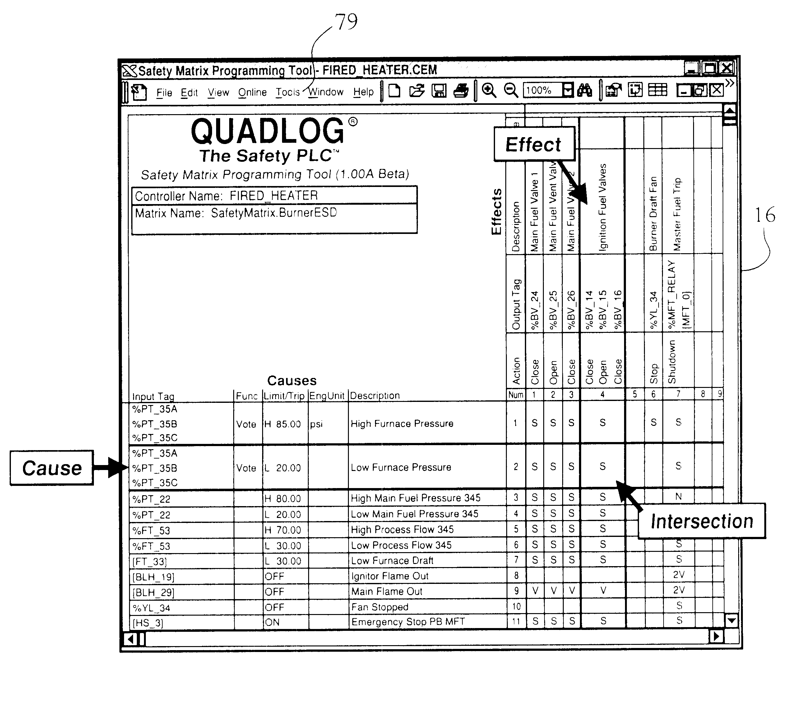
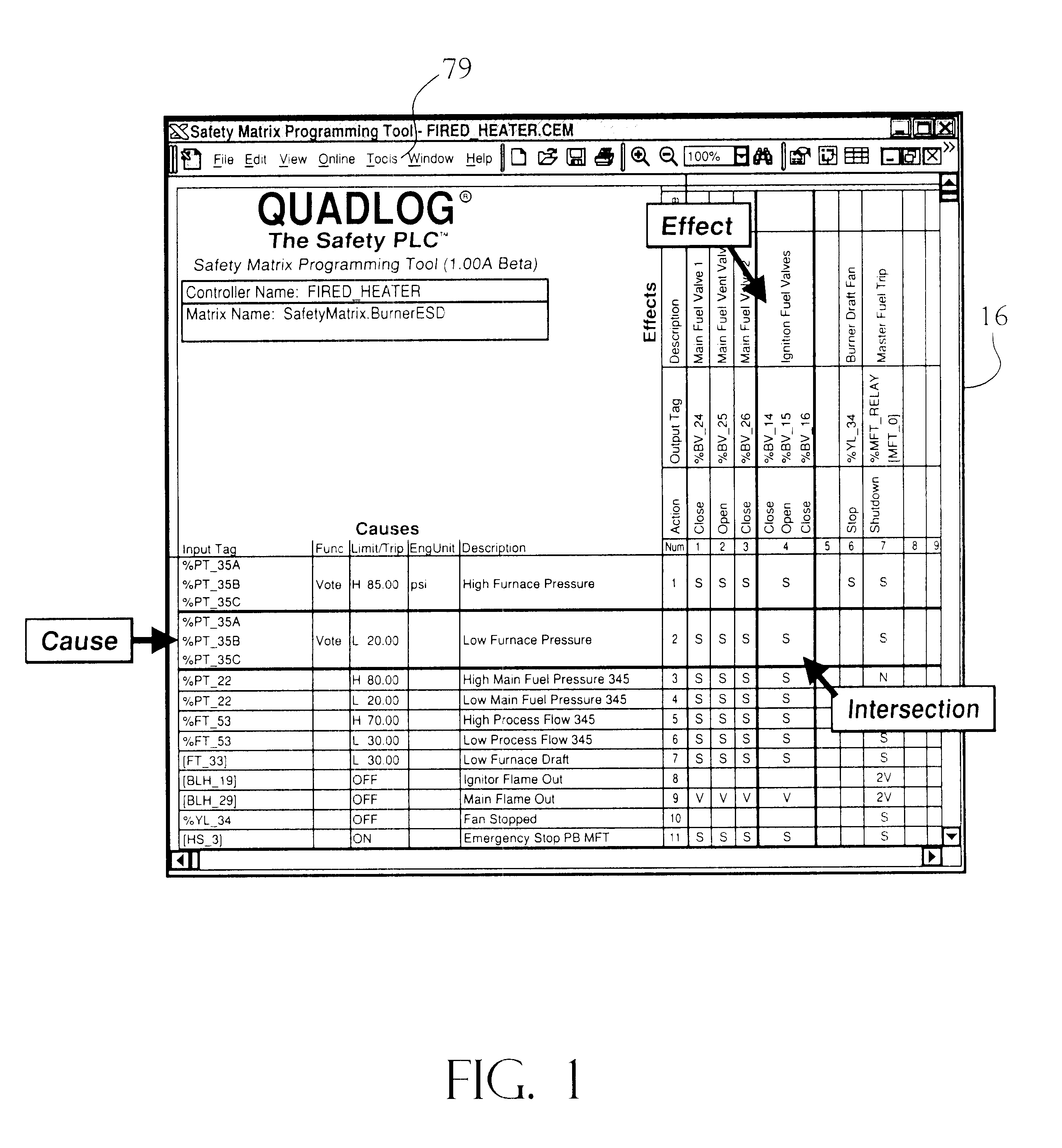
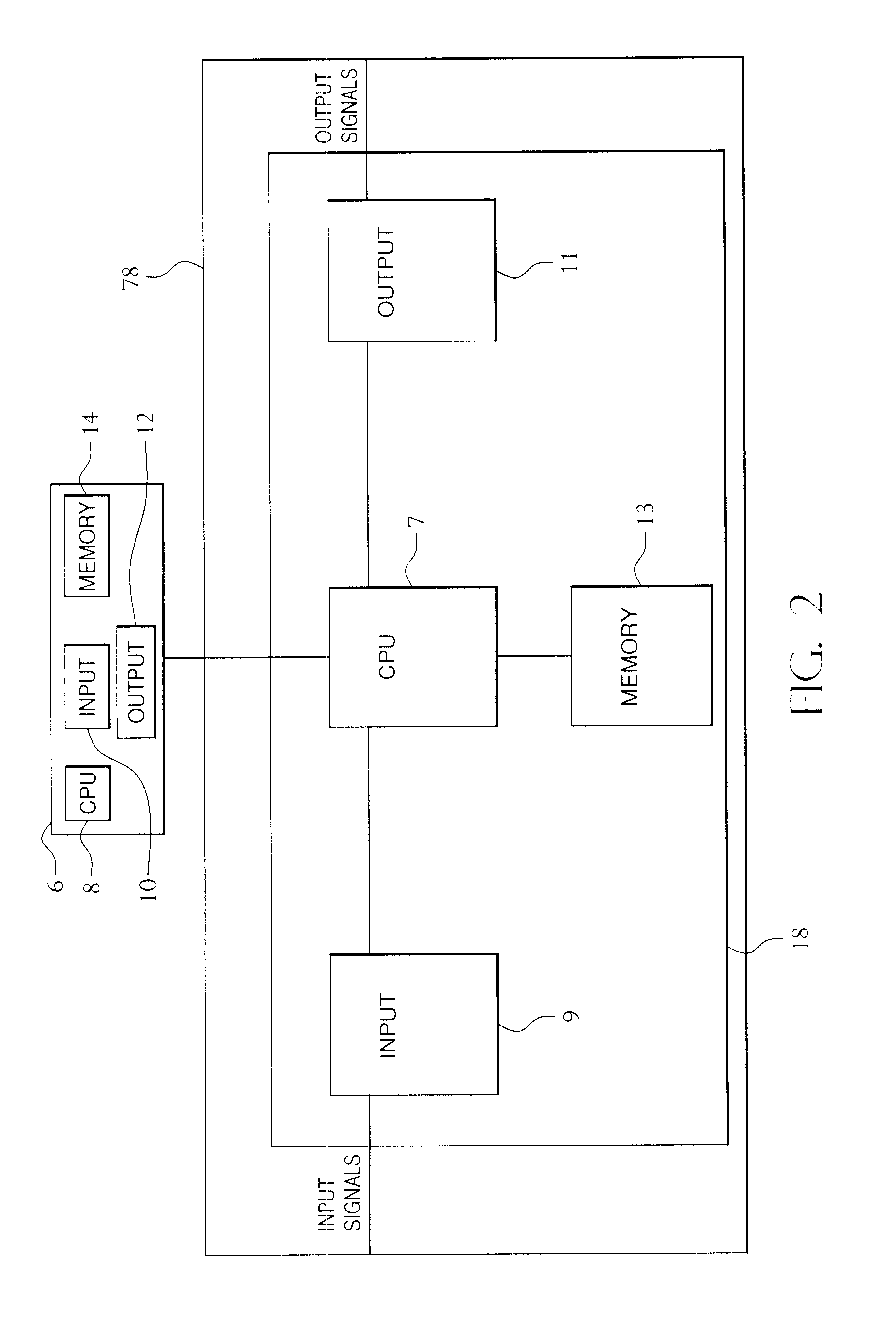
The present invention enables a user to graphically create and configure a matrix with data that defines input elements or variables that require monitoring, output responses to changes in the input elements / variables, also referred to as input parameters, being monitored and the relationship between the input elements / variables and the output responses. Once the matrix is created, the user can transfer the defining data to a programmable logic controller 78 to generate logic to implement the matrix. The programmable logic controller 78, as illustrated in FIG. 2 may comprise a central processing unit 7, an input device 9, an output device 11, and a memory element 13. The memory element 13 may be a combination of read only memory (ROM) and random access memory (RAM). As illustrated in FIG. 3, the programmable logic controller 78 includes a matrix functional unit 18. The matrix functional unit 18 includes at least one input functional unit for the input elements / variables, at least on...


PUM


Abstract

The present invention provides a system and method for graphically generating logic for a cause and effects matrix. The present invention includes creating a matrix for defining the elements of the system that require monitoring, the responses to changes in the monitored elements and the relationship between the elements and the responses and automatically creating logic to implement the matrix. The system includes a general purpose digital computer that incorporates a matrix programming tool to input data defining the matrix and generate a matrix database. The tool also transfers the matrix database to a programmable logic controller. The programmable logic controller includes a matrix functional unit. The matrix functional unit includes several predefined, configurable functional units for establishing the logic pathways to implement the matrix. The predefined, configurable functional units include a cause functional unit, an effects functional unit and an intersection functional unit. Once the predefined functional units receives the matrix database information from the computer the logic pathways to implement the matrix are automatically established.

Description

FIELD OF THE INVENTIONThe present invention is directed to a system and method for generating logic for a Cause and Effects Matrix which may be used in a monitoring system. The present invention includes creating a matrix for defining the elements of the system that require monitoring, the responses to changes in the monitored elements and the relationship between the elements and the responses and automatically creating logic to implement the matrix. The present invention is directed to a system and method for graphically generating the Cause and Effects Matrix and implementing the matrix utilizing predefined logic as defined by the programming environment of the monitoring system, for example function blocks, to establish a particular cause, a particular effect and a relationship therebetween.BACKGROUND OF THE INVENTIONCause and effects matrices are used in many industries for many purposes. The basic concept of a Cause and Effects Matrix is to provide a means for monitoring the a...

Claims


Application Information

Patent Timeline
IPC IPC(8): G09G5/00G06F17/24G06F3/00G05B19/418
CPCG05B19/4189Y10S715/966Y02P90/02
Inventor KLAPPER, JOHN P.LELIEVRE, DANIEL
Owner SIEMENS ENERGY & AUTOMATION INC
Features
  • Generate Ideas
  • Intellectual Property
  • Life Sciences
  • Materials
  • Tech Scout
  • Unparalleled Data Quality
  • Higher Quality Content
  • 60% Fewer Hallucinations
Learn More