

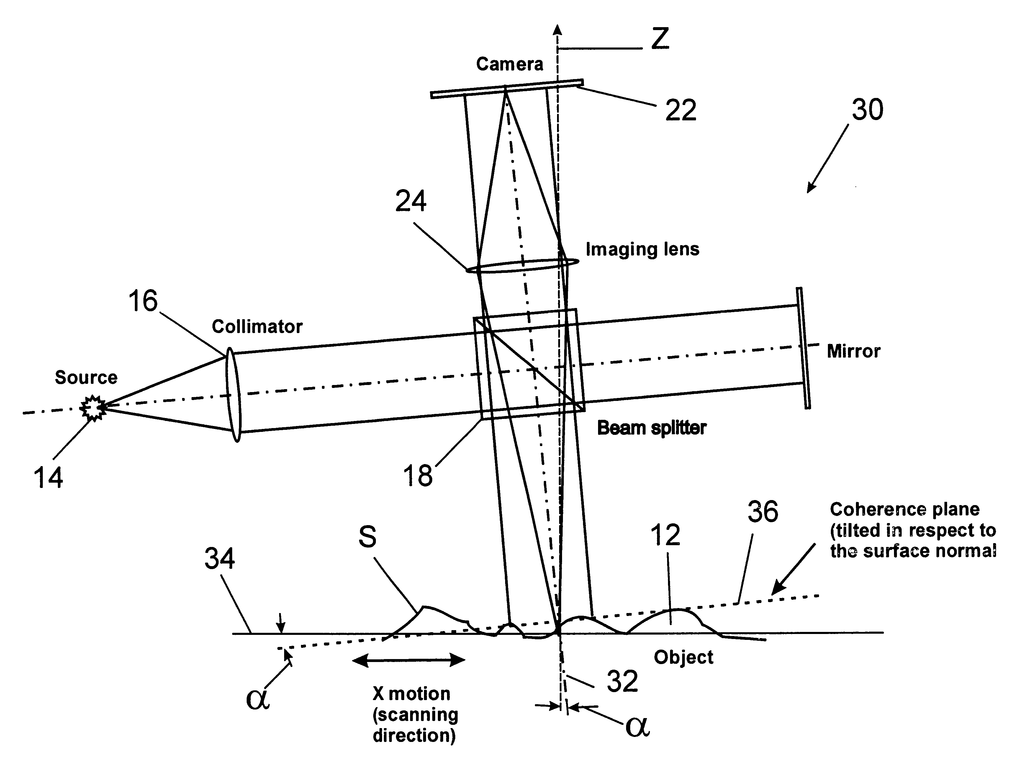
Lateral-scanning interferometer with tilted optical axis
an interferometer and tilting technology, applied in the field of interferometry, can solve the problems of mechanical undesirable shift-and-hold motion of the stepping method, slowing down the data acquisition process, and no longer being generally preferred in the industry
- Summary
- Abstract
- Description
- Claims
- Application Information
AI Technical Summary
Problems solved by technology
Method used
Image

Examples
Embodiment Construction
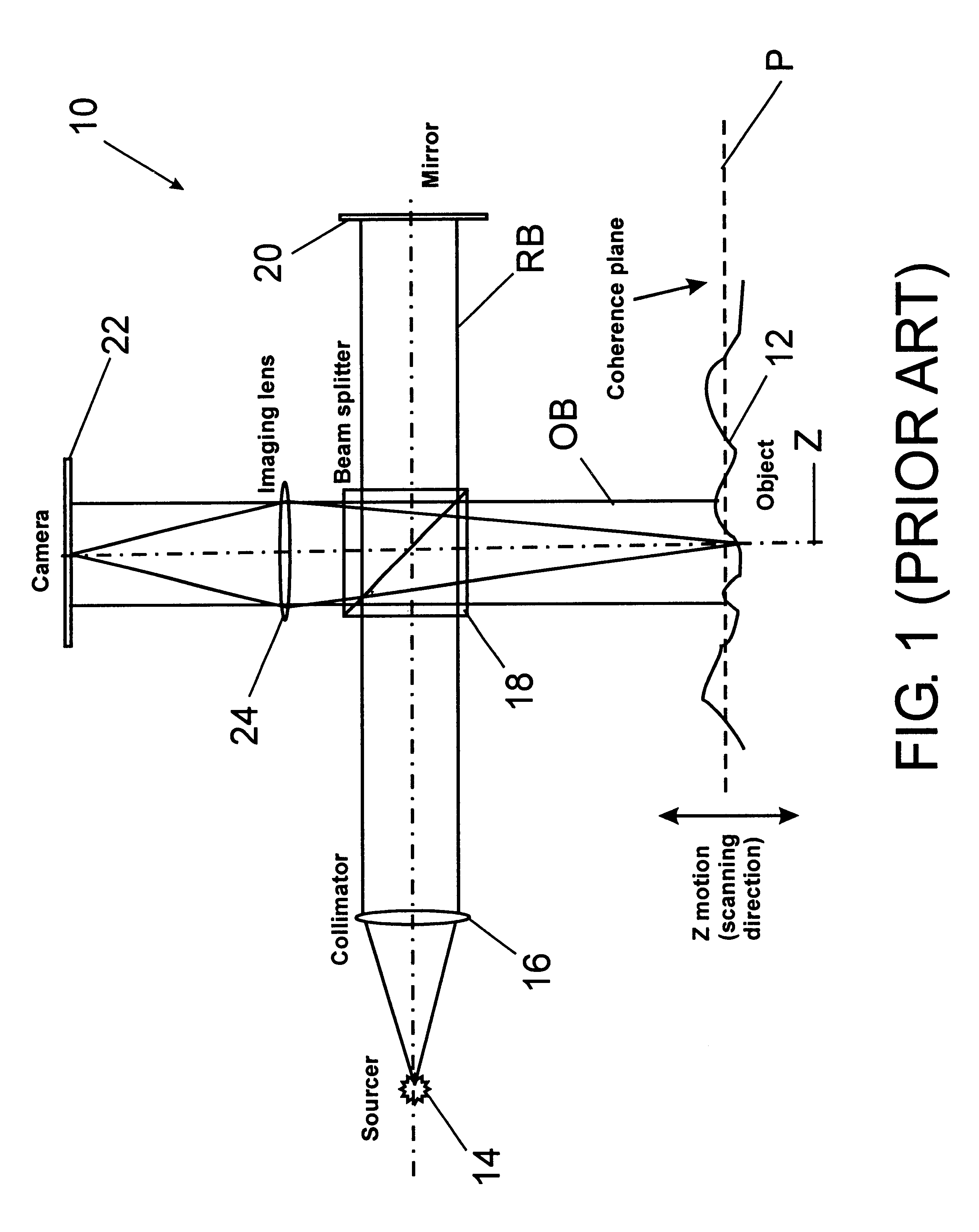
The invention is based on the realization that the effective testing range of an interferometer can be expanded by continuously scanning a tilted sample surface or fixture across the objective's field of view. By tilting the objective's optical axis with respect to the sample stage and by scanning the sample across the tilted coherence plane of the instrument, the resulting relative vertical scan produces a sequence of interferograms equivalent to conventional vertical-scanning interferometry. The invention is described in terms of white-light interferometric apparatus, but it is understood that any broadband light suitable to practice VSI interferometry would be appropriate for the invention. Moreover, as one skilled in the art would readily understand, the invention could also be adapted for implementation to PSI measurements, both with narrow- and broad-bandwidth light, subject only to successful resolution of the 2.pi. ambiguity problem associated with all PSI measurements. Ther...
PUM
 Abstract
Description
Claims
Application Information