System and method of controlling a legged locomotion robot

a technology of moving control apparatus and method, which is applied in the direction of electric programme control, program control, instruments, etc., can solve the problems of difficult control of upright posture, difficult to recover upright position of upright robot, and more unstable bipedal movement in upright posture, etc., to achieve good control, high accuracy, and stable posture

Active Publication Date: 2011-02-01
SONY CORP +1
View PDF18 Cites 52 Cited by
  • Summary
  • Abstract
  • Description
  • Claims
  • Application Information

AI Technical Summary

Benefits of technology

[0047]On the other hand, since acceleration sensors are provided at each of controlled-object points set at a plurality of locations or points on the robot, an equation can be introduced using accurate acceleration data and with a reduced amount of calculation. As a result, the trajectory can be well corrected even for an operation which should be done at a high speed, such as jumping and running.
[0061]As a result, a ZMP equation can be formulated directly at the foot nearest to a ZMP position and thus there can be implemented a stricter and quick control of the robot for a stable posture, independent of the above-mentioned conditions.
[0064]In such a case, necessary control parameters for introduction of a ZMP equation (or dynamic equation) can be measured directly. As a result, a strict movement control can be implemented with a high response, not on the assumption that the robot is rigid enough not to be deformable with any external force applied.
[0070]Also, the sensors distributed over the robot may be connected in series to each other to sequentially add, at each of individual control points and along the connection route, moment terms and external force terms calculated based on sensor information at the individual control points. A sum of these terms can be efficiently calculated to calculate a ZMP equation and dynamic equation at a high speed.

Problems solved by technology

The bipedal movement in an upright posture is more unstable and difficult to control in attitude and walking than the movements on crawlers, four or six feet.
The “falling” means an interruption of a job the robot has been doing.
The robot will take considerable labor and time to recover its upright position from the tipping condition and resume the job.
Also, the falling will possibly cause a critical damage to the robot itself and also to an object with which the robot has collided in falling.
Therefore, the control of the robot to take a stable posture in walking or working is one of the most important technical problems in designing and development of a legged locomotion robot.
In case only the above calculation based on the ZMP equation is used for controlling the robot to take a stable posture, the amount of calculation is larger, the load of data processing is larger and thus a longer time is required for the calculation.
Further, since acceleration data is indirectly acquired, it cannot be accurate and thus it is difficult for the robot to implement an action for which the robot trajectory has to be corrected quickly and real-time, such as jump or running.
In this case, however, the data calculation will take an excessively long time, which will lead to an increased cost of manufacturing.
However, with the control system adopting the above arrangement of the sensors, it is difficult to control the robot movement by directly measuring positions and accelerations of all points on the robot in addition to the acceleration of the origin of the local coordinate.
Therefore, on a gravel road whose surface will move when applied with a force and torque, a thick-piled carpet or on a tile floor in a house, slippery with no sufficient friction coefficient for translation, namely, in case the above assumptions are not assured, the conventional robot designed with a consideration given to the flexibility of the robot structure itself to implement a whole-body movement including a stable walking (movement) and jump will not perform well so long as its movement control system is based on the above assumptions.

Method used


Image

  • System and method of controlling a legged locomotion robot
  • System and method of controlling a legged locomotion robot
  • System and method of controlling a legged locomotion robot

Examples


Embodiment Construction

[0095]The present invention will be described in detail below concerning the embodiments thereof with reference to the accompanying drawings.

[0096]A. Mechanical Construction of the Legged Locomotion Robot

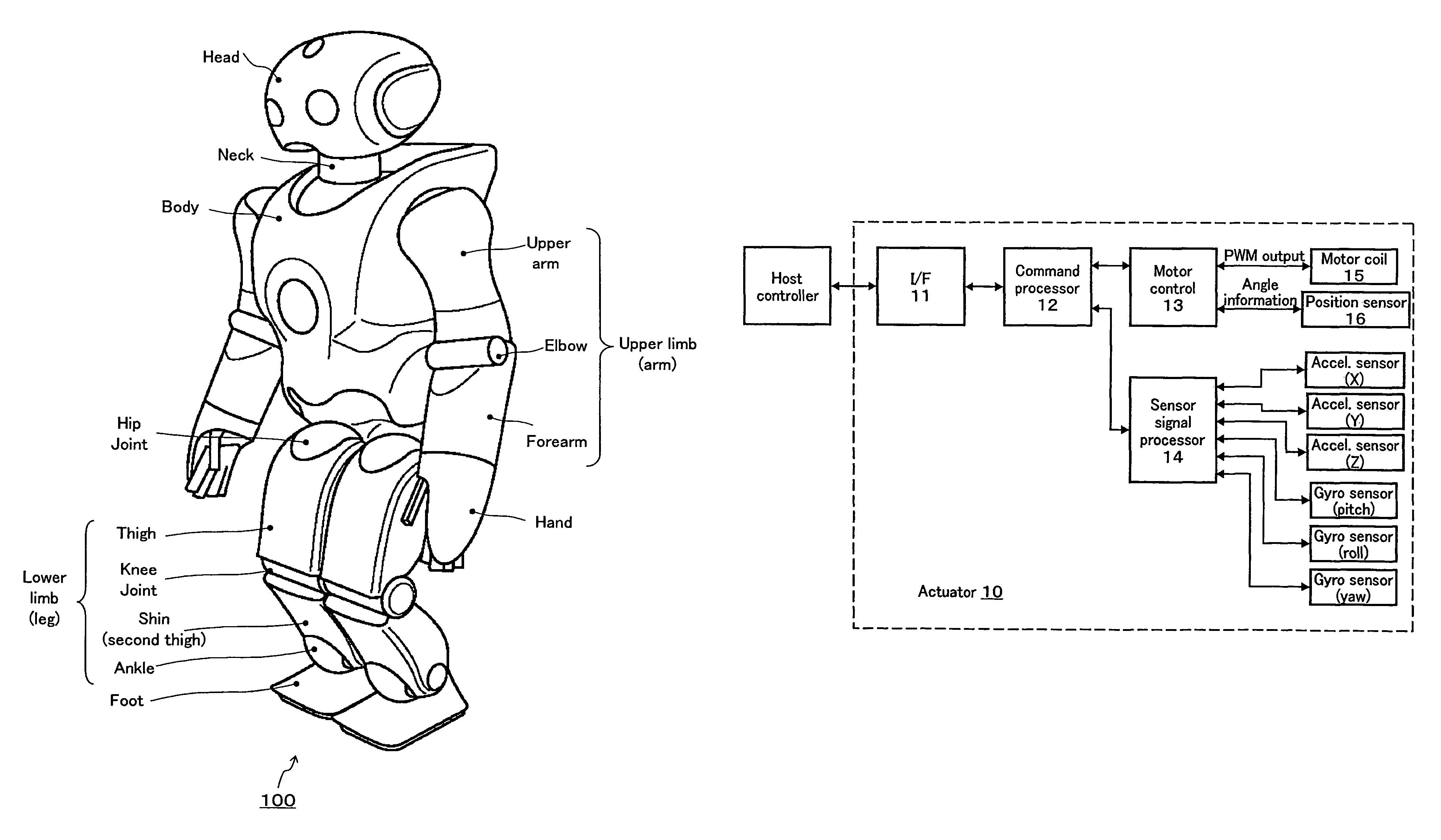
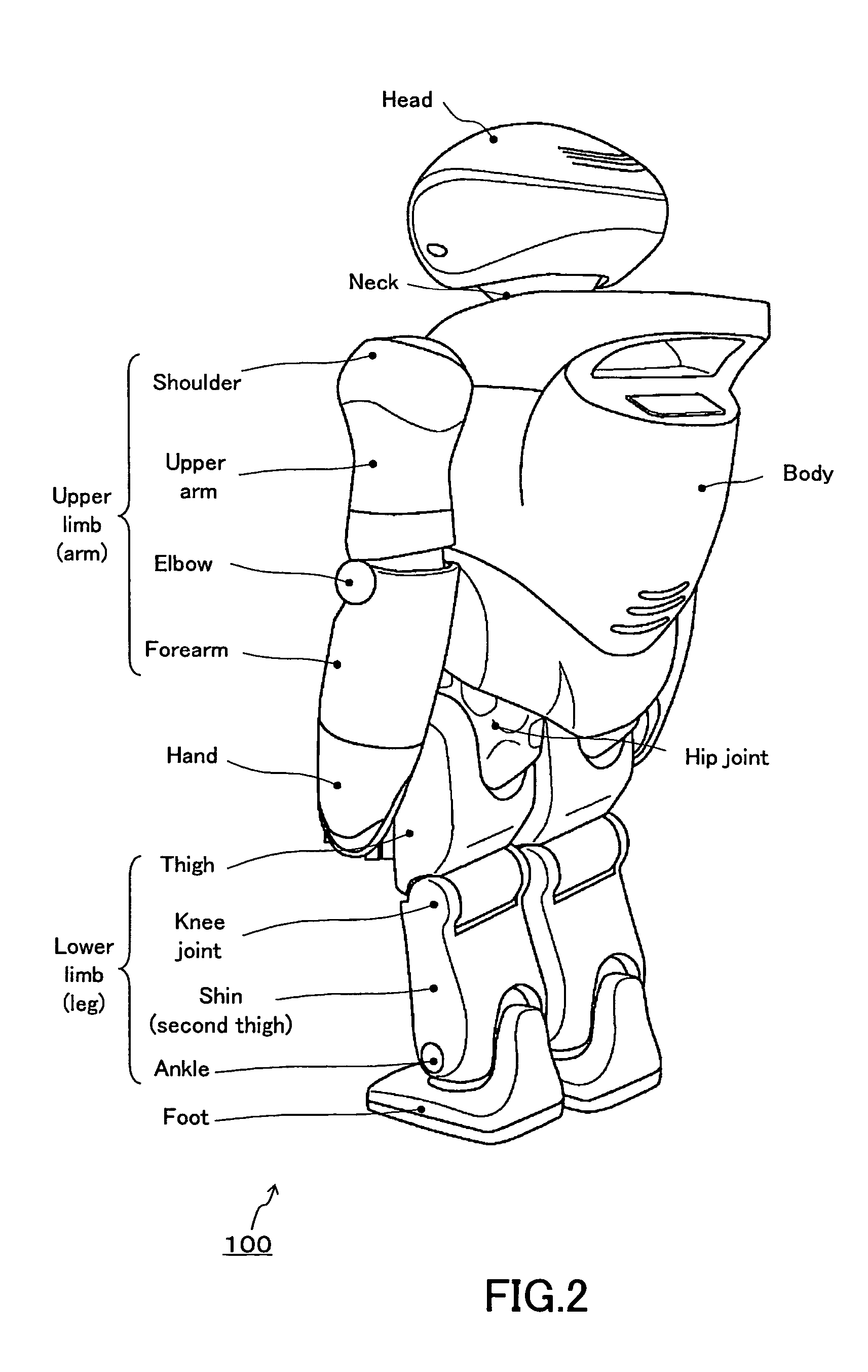
[0097]FIGS. 1 and 2 are front and rear views, respectively, of an embodiment of the humanoid type legged locomotion robot 100 according to the present invention. It is in upright position. As shown, the legged locomotion robot 100 includes a body, head, right and left upper limbs, and right and left lower limbs for the legged movement. A control unit (not shown) built in the body provides a system control of the entire robot.

[0098]Each of the right and left lower limbs includes a thigh, knee joint, second thigh, ankle and foot. The lower limb is coupled by a hip joint to the bottom of the trunk. Each of the right and left upper limb includes an upper arm, elbow joint and forearm. The upper limb is coupled by a shoulder joint to each upper edge of the trunk. Also, the head is coupled...


PUM


Abstract

The lumbar part of a robot as a controlled-object point where the mass amount becomes maximum is set as the origin of a local coordinate, an acceleration sensor is disposed at the controlled-object point to directly measure the attitude and acceleration at that position to control the robot to take a stable posture on the basis of a ZMP. Further, at each foot which touches the walking surface, there are provided a floor reaction force sensor and acceleration sensor to directly measure a ZMP and force, and a ZMP equation is formulated directly at the foot nearest to a ZMP position. Thus there can be implemented a stricter and quick control of the robot for a stable posture.

Description

TECHNICAL FIELD[0001]The present invention generally relates to a movement controlling apparatus and method for a legged locomotion robot having at least a plurality of moving legs, a sensor system for a legged locomotion robot, and a mobile device, and more particularly to a movement controlling apparatus and method for a legged locomotion robot, in which a ZMP (zero-moment point) is adopted as a stability criterion, a sensor system for a legged locomotion robot, and a mobile device.[0002]More specifically, the present invention is directed to a movement controlling apparatus and method for a legged locomotion robot, in which a ZMP equation introduced based on measurements from sensors mounted at various portions of a robot is used to identify an unknown external force moment and unknown external force for controlling the movement of the robot, a sensor system for a legged locomotion robot, and a mobile device, and more particularly to a movement controlling apparatus and method fo...

Claims


Application Information

Patent Timeline
Patent Type & Authority Patents(United States)
IPC IPC(8): G05B15/00G05B19/00B25J13/08B62D57/02B62D57/032
CPCB25J13/085B62D57/032B62D57/02B25J13/088G05D1/08
Inventor NAGASAKA, KENICHIROYAMAGUCHI, JINICHISHIMIZU, SATORUKUROKI, YOSHIHIRO
Owner SONY CORP
Why Eureka
Try Eureka