
Fuel pressure control apparatus of internal combustion engine

a technology of internal combustion engine and control apparatus, which is applied in the direction of electric control, machines/engines, fuel injecting pumps, etc., can solve the problems of increasing, reducing, and increasing the integral term,

Inactive Publication Date: 2002-09-17
TOYOTA JIDOSHA KK
View PDF6 Cites 26 Cited by
  • Summary
  • Abstract
  • Description
  • Claims
  • Application Information

AI Technical Summary

Benefits of technology

When the amount of fuel delivered from the fuel pump is approximate to or equal to the maximum value, for example, at the time of a start of the engine, the fuel pressure is not rapidly increased even if the integral term is updated so as to increase the fuel pressure to the target value. Accordingly, the integral term may be undesirably changed (i.e., increased) to an excessively large value that causes an increase in the amount of fuel delivered. With the above arrangement of the invention, however, the upgrading of the integral term in a direction as to increase the amount of fuel delivered is inhibited when the amount of fuel delivered from the fuel pump is close to or equal to the maximum value, and therefore the integral term is prevented from being excessively changed or increased to an excessively large value that causes an increase in the amount of fuel delivered. It is thus possible to suppress or avoid so-called "overshoot" that would otherwise occur when the actual fuel pressure increases to a great extent above the target value due to the excessively increased integral term that had been updated while the amount of fuel delivered from the fuel pump was close to or equal to the maximum value.
With the above arrangement, the integral term is not only inhibited from being updated to larger values that will increase the amount of fuel delivered from the fuel pump when the amount of delivered fuel almost reaches the maximum value, but also is positively updated or reset to a smaller value that will reduce the amount of fuel delivered. It is therefore possible to further appropriately prevent the integral term from excessively changing in a direction as to increase the amount of fuel delivered.

Problems solved by technology

If this controlled variable increases, the amount of fuel delivered from the high-pressure fuel pump increases, resulting in an increase, in the fuel pressure.
Conversely, if the controlled variable decreases, the amount of fuel delivered from the high-pressure fuel pump decreases, resulting in a decrease in the fuel pressure.
However, since it takes substantial time to reduce the fuel pressure, the integral term becomes excessively small before the actual fuel pressure is reduced down to the target pressure.
As a result, the fuel pressure is further reduced, thereby causing so-called "undershoot".
In that case, the integral term tends to be an excessively large value.
Therefore, the controlled variable used for controlling the amount of fuel delivered from the high-pressure fuel pump, which is obtained after the actual fuel pressure reaches the target value, deviates from the required value in such a direction as to increase the amount of fuel delivered, because of the excessively increased integral term.
As a result, the actual fuel pressure exceeds the target value to an excessively large extent, namely, so-called "overshoot" occurs, resulting in a problem such as deterioration of the combustion state of the internal combustion engine.
Accordingly, the integral term may be undesirably changed (i.e., increased) to an excessively large value that causes an increase in the amount of fuel delivered.

Method used


Image

  • Fuel pressure control apparatus of internal combustion engine
  • Fuel pressure control apparatus of internal combustion engine
  • Fuel pressure control apparatus of internal combustion engine

Examples


Embodiment Construction

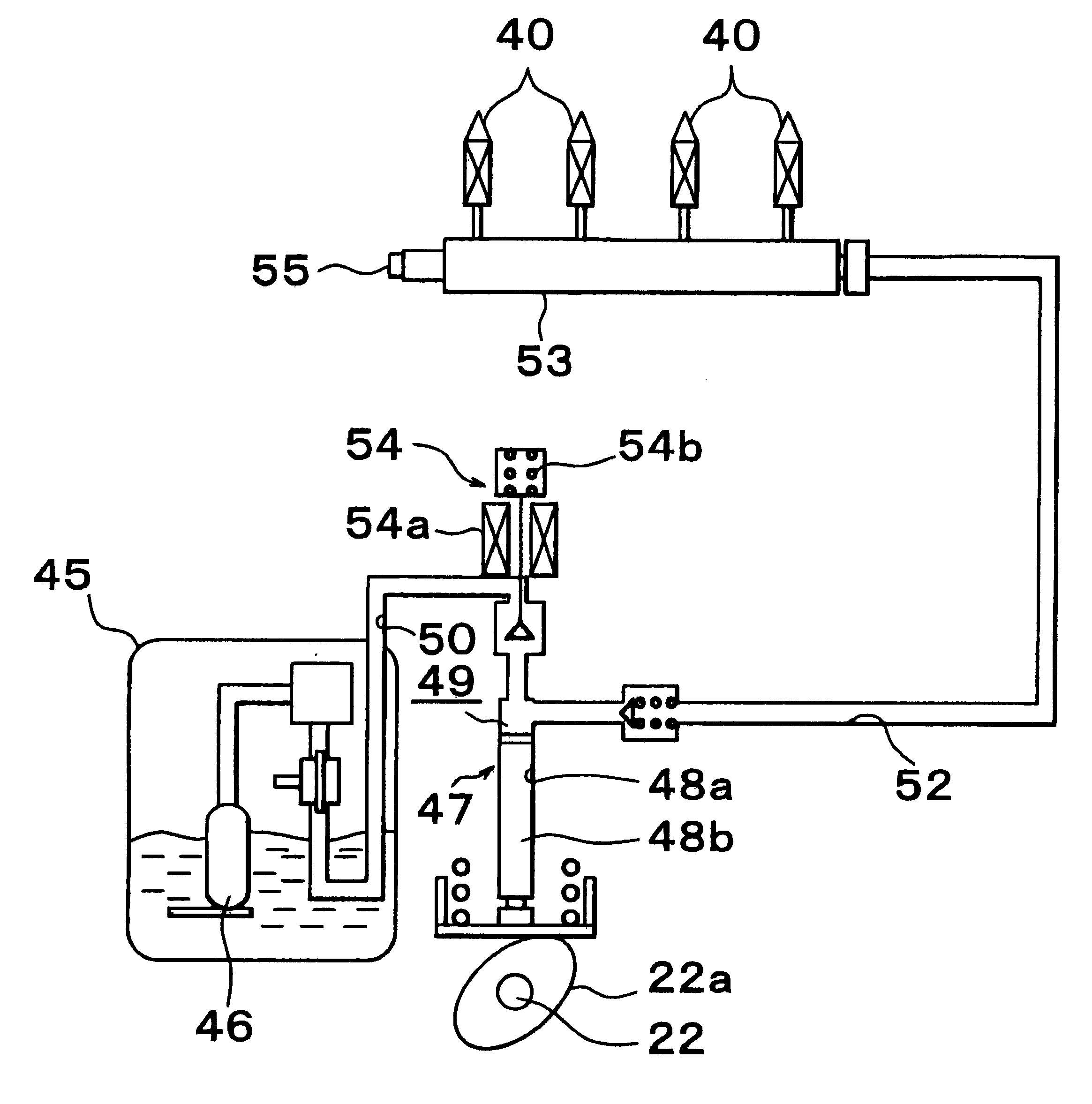
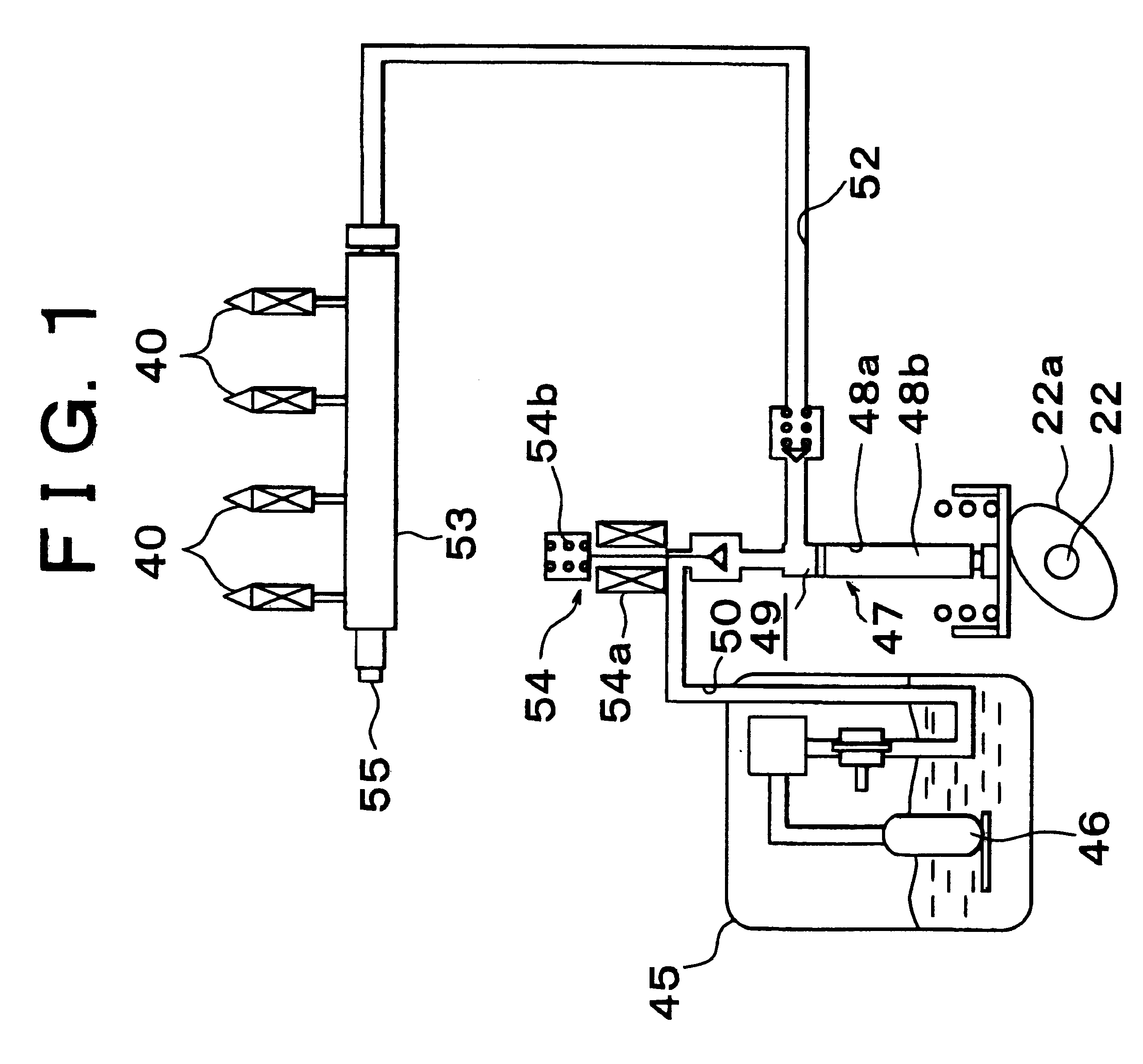
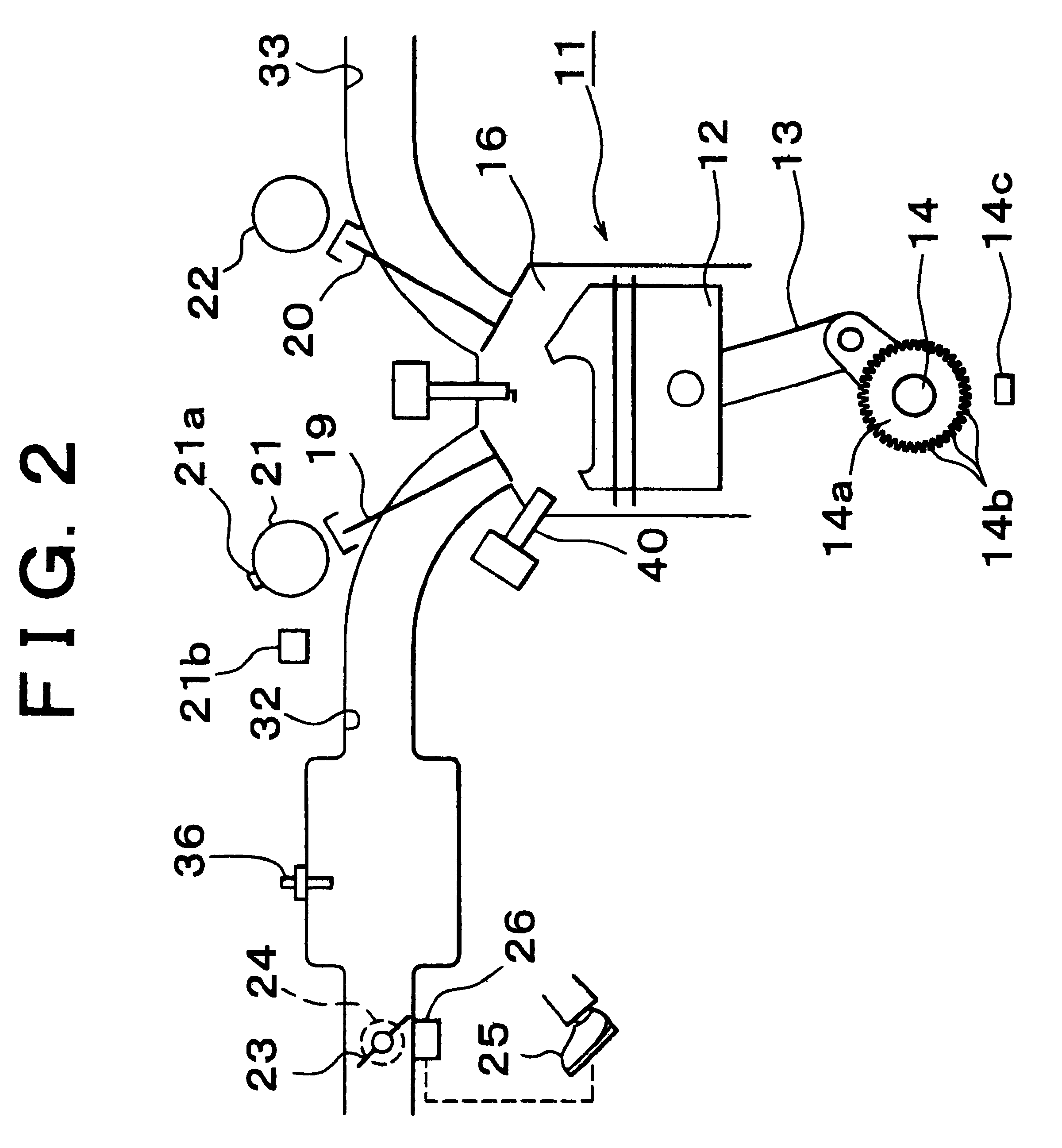
A preferred embodiment of the invention when it is applied to an automotive engine will be described hereinafter with reference to FIGS. 1 to 6.

Referring first to FIG. 2, an engine 11 has a piston 12 that is connected to a crankshaft 14 via a connecting rod 13. Reciprocating movements of the piston 12 are converted into rotary motion of the crankshaft 14 by the connecting rod 13. A signal rotor 14a having a plurality of protrusions 14b is attached to the crankshaft 14. A crank position sensor 14c is provided at one side of the signal rotor 14a. The sensor 14c is adapted to output a signal in the form of pulses corresponding to respective protrusions 14b during rotation of the crankshaft 14.

An intake passage 32 and an exhaust passage 33 are connected to a combustion chamber 16 of the engine 11. The intake passage 32 and the combustion chamber 16 are brought into communication with each other or are disconnected or shut off from each other by opening or closing an intake valve 19, whi...


PUM


Abstract

A fuel pressure control apparatus and method controls a pressure of fuel that is delivered from a fuel pump to a fuel pipe in an internal combustion engine of a vehicle. A controller of the fuel pressure control apparatus calculates a controlled variable based on at least an integral term that is updated in accordance with a difference between an actual fuel pressure in the fuel pipe and a target value thereof; and controls an amount of the fuel delivered from the fuel pump in a feedback manner, using the controlled variable, so that the actual fuel pressure approaches the target value. During the control of the fuel pressure, the controller inhibits updating of the integral term to a value that results in an increase in the amount of the fuel delivered from the fuel pump, when the amount of the fuel delivered is approximate to or equal to a maximum value thereof.

Description

INCORPORATION BY REFERENCEThe disclosure of Japanese Patent Application No. 2000-082312 filed on Mar. 23, 2000, including the specification, drawings and abstract, is incorporated herein by reference in its entirety.1. Field of the InventionThe invention relates to a fuel pressure control apparatus of an internal combustion engine.2. Description of Related ArtGenerally, in an internal combustion engine of the type in which fuel is directly injected into a combustion chamber, the fuel supplied to a fuel injection valve or valves is pressurized by a high-pressure fuel pump, so that the fuel pressure is increased to a value (target value) that permits fuel injection against the pressure in the combustion chamber. The fuel pressure is thus controlled by driving the high-pressure fuel pump in a controlled manner based on a controlled variable that is calculated based on the actual fuel pressure in a fuel pipe and a target value thereof, and by controlling the amount of fuel delivered fro...

Claims


Application Information

Patent Timeline
Patent Type & Authority Patents(United States)
IPC IPC(8): F02D41/14F02D41/38F02M37/00F02D41/04F02M55/02F02M59/20
CPCF02D41/1482F02D41/3845F02D2041/1409F02D2041/1422F02D2250/31
Inventor DEMURA, TAKAYUKIMIZUNO, HIROYUKIYONEZAWA, KOICHI
Owner TOYOTA JIDOSHA KK
Learn More