Eureka AIR delivers breakthrough ideas for toughest innovation challenges, trusted by R&D personnel around the world.

Apparatus for recycling wasted heat using waste hot water

Inactive Publication Date: 2010-10-28
GOMYUNG ENERTECH
View PDF7 Cites 27 Cited by
  • Summary
  • Abstract
  • Description
  • Claims
  • Application Information

AI Technical Summary

Benefits of technology

[0009]In order to overcome the above problems, it is an object of the present invention to provide an apparatus for recycling wasted heat, using waste hot water, which saves energy and prevents deterioration of absorption efficiency of wasted heat due to easy maintenance by preheating cold water that is supplied to a shower, using the wasted heat of waste hot water.
[0017]According to the present invention, it is friendly to the environment by reducing the amount of fuel consumed to supply hot water and it is possible to reduce the fuel cost by the reduced amount of fuel consumption. Further, since the structure is simple and the manufacturing cost is low, maintenance, such as cleaning or replacing, is easy.

Problems solved by technology

Most hot water used for a bath or a shower is discharged through a drain-outlet, but it is undesirable in terms of efficient use of energy to discharge the waste hot water outside a bathhouse without recycling the heat of the waste hot water, because the heat of the discharged waste hot water has temperature of 30° C. or more.
However, apparatuses for recycling wasted heat in the related art had a problem in that thermal efficiency is easily deteriorated, because the structure is complicated and foreign substances are easily gathered on the internal heat transfer surface.
Therefore, even though the heat transfer surface should be frequently cleaned, it was difficult to clean it, because the structure is a covered type.
Meanwhile, it was substantially difficult to install a large apparatus for recycling wasted heat of the related art in small bathrooms of houses in terms of the cost and structure and research for an apparatus for recycling wasted heat, which has a simple structure and can be achieved at a low cost such that it can be installed in houses, are still insufficient.

Method used


Image

  • Apparatus for recycling wasted heat using waste hot water
  • Apparatus for recycling wasted heat using waste hot water
  • Apparatus for recycling wasted heat using waste hot water

Examples


Embodiment Construction

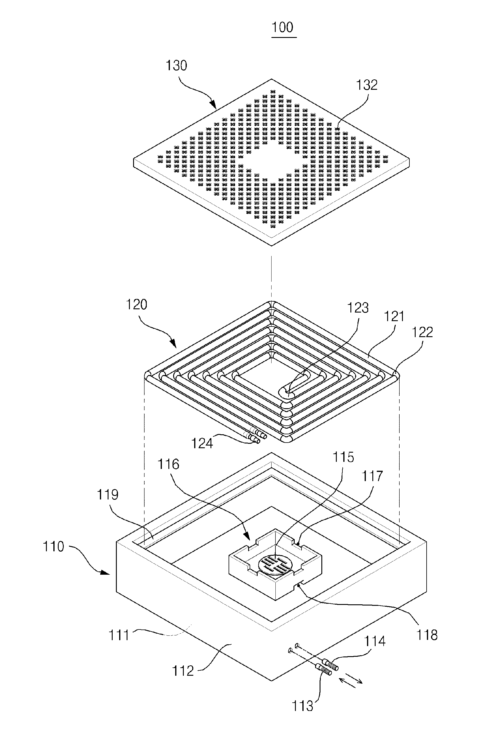
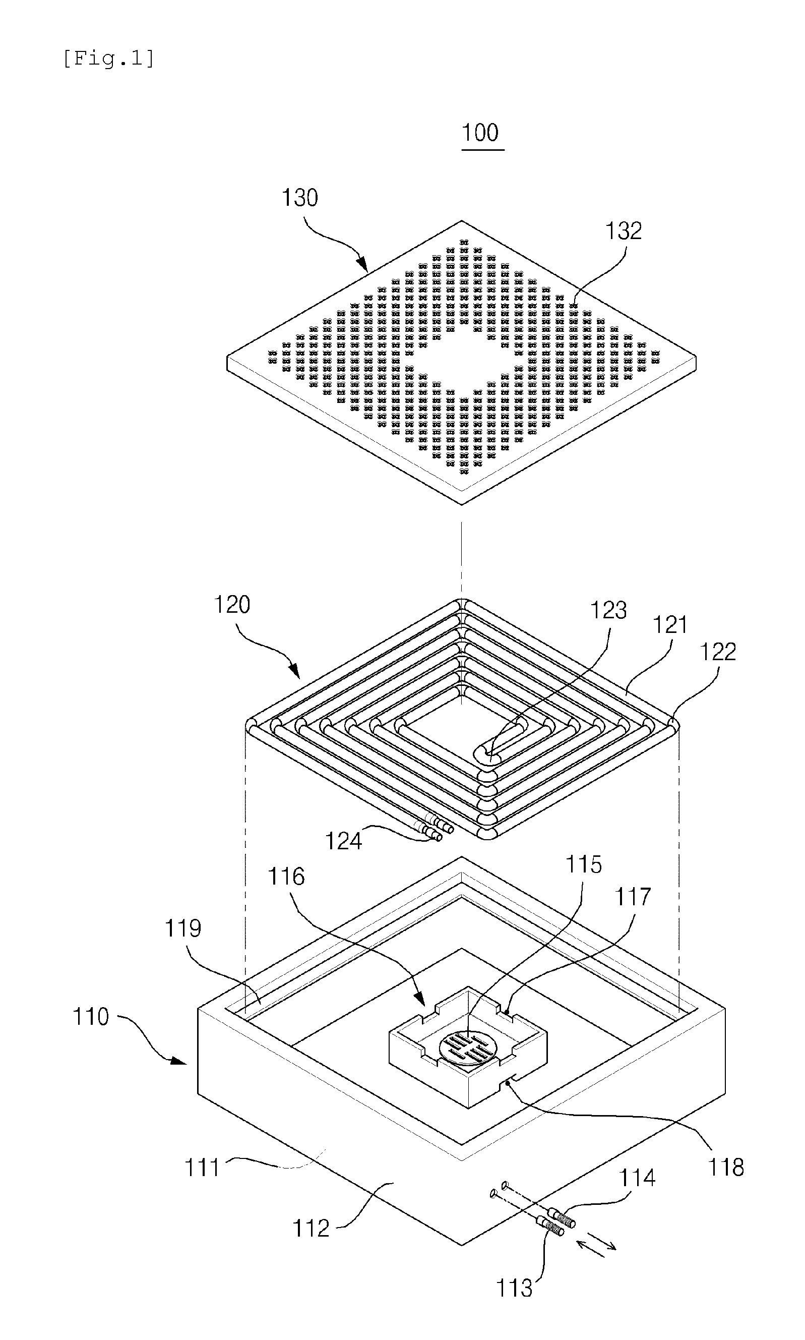
[0023]Hereinafter, preferred embodiments of the present invention will be described in detail with reference to the accompanying drawings. First of all, it is to be noted that in giving reference numerals to elements of each drawing, like reference numerals refer to like elements even though like elements are shown in different drawings. Detailed descriptions may not be provided if it is determined those may make the aspect of the present invention unclear. Hereinafter, the preferred embodiment of the present invention will be described, but it will be understood to those skilled in the art that the spirit and scope of the present invention are not limited thereto and modifications and changes can be made in various ways.

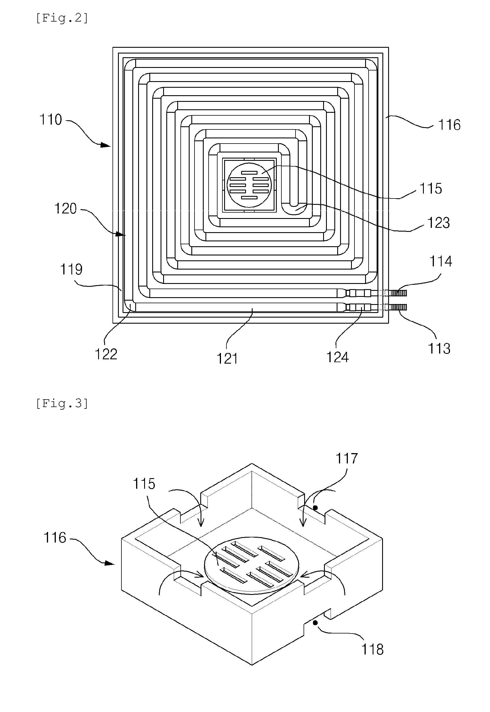
[0024]FIG. 1 is an exploded perspective view of an apparatus for recycling wasted heat using waste hot water according to an embodiment of the present invention, FIG. 2 is a plan view of the apparatus for recycling wasted heat using waste hot water, with the upper c...


PUM


Abstract

The present invention relates to an apparatus for recycling wasted heat using waste hot water that includes: a tub that charges and discharges waste hot water; a heat exchange unit that transfers the heat of waste hot water to cold water supplied to a shower bat; and an upper cover that the open upper portion of the tub, and is friendly to the environment by reducing the amount of fuel consumed to supply hot water and it is possible to reduce the fuel cost by the reduced amount of fuel consumption.

Description

BACKGROUND OF THE INVENTION[0001]1. Field of the Invention[0002]The present invention relates to an apparatus for recycling wasted heat using waste hot water. In detail, the present invention relates to an apparatus for recycling wasted heat using waste hot water, which collects waste hot water that is discharged after being used from a shower or bath and then preheats cold water to be supplied for a shower, using heat of the waste hot water.[0003]2. Description of the Related Art[0004]In general, hot water that is used in houses or bathhouses is supplied to waterworks or showers through hot water supply lines after water at the normal temperature is heated by a variety of boilers using fossil fuel or electric energy.[0005]Most hot water used for a bath or a shower is discharged through a drain-outlet, but it is undesirable in terms of efficient use of energy to discharge the waste hot water outside a bathhouse without recycling the heat of the waste hot water, because the heat of t...

Claims


Application Information

Patent Timeline
IPC IPC(8): F28D15/00
CPCE03F5/04F24D17/0005F24D2200/20E03C2001/005F28D21/0012F28F2210/10Y02B30/566F28D7/04Y02B30/18Y02B30/56F28D7/00F28D15/00
Inventor KIM, YONG IL
Owner GOMYUNG ENERTECH
Why Eureka
Eureka Blog
Learn More