Process and apparatus for separation of hydrocarbons from liquefied natural gas

a technology of hydrocarbon separation and hydrocarbons, which is applied in the direction of absorption purification/separation, liquefaction, lighting and heating apparatus, etc., can solve the problems of affecting the operation of the deethanizer, and damaging the deethanizer, so as to achieve low energy and low cost without impairing the ease and reliability of operation. , the effect of low cos

Active Publication Date: 2006-12-14
TOYO ENG CORP
View PDF21 Cites 25 Cited by
  • Summary
  • Abstract
  • Description
  • Claims
  • Application Information

AI Technical Summary

Benefits of technology

[0033] According to the present invention, there is provided a process and apparatus capable of separating hydrocarbons such as

Problems solved by technology

However, the easiness and reliability of operation are impaired because the overhead gas of the deethanizer or depropanizer is condensed by the liquefied natural gas which is a feed fluid to the demethanizer.
For example, when fluctuation occurs in the feed amount of liquefied natural gas, the fluctuation immediately affects the deethanizer, disturbing the operation of the deethanizer.
Sin

Method used


Image

  • Process and apparatus for separation of hydrocarbons from liquefied natural gas
  • Process and apparatus for separation of hydrocarbons from liquefied natural gas
  • Process and apparatus for separation of hydrocarbons from liquefied natural gas

Examples


example 1

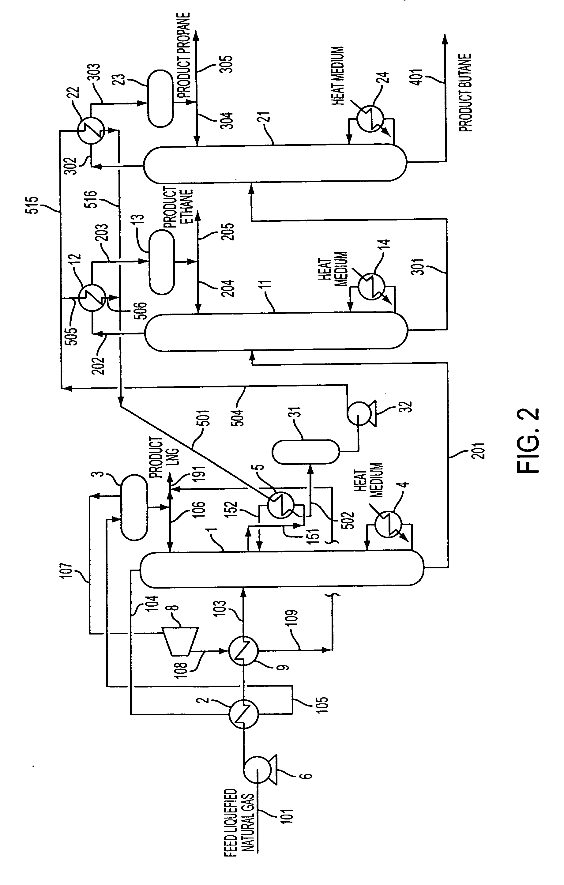
[0074] In this Example is explained a process having a flow shown in FIG. 2, for recovering ethane, propane and butane from feed liquefied natural gas. Here, feed liquefied natural gas 101 having a pressure of 0.5 MPa (A) and a temperature of −152° C. is introduced into the present process at a flow rate of 625 tons / hour. The feed liquefied natural gas had a composition shown in Table 1.

TABLE 1Composition of feed liquefied natural gas (mol %)N20.46Methane89.79Ethane6.47Propane2.23Butane1.05Components heavier than butane0.00Total100.00

[0075] The feed liquefied natural gas is pressurized by feed liquefied natural gas pump 6 and undergoes heat exchange with the overhead gas of demethanizer at overhead gas condenser 2 and pressurized residue gas heat exchanger 9. Thereby, demethanizer feed 103 is heated up to about −100° C. and fed to the 12th tray of demethanizer 1.

[0076] The demethanizer has trays of 23 stages in terms of theoretical stage number inside and is operated at the top u...

example 2

[0079] In this Example, as shown in FIG. 3, two intermediate-stage heat exchangers for demethanizer are installed in order to give the heat transfer medium temperature levels more appropriate for cooling medium used in the overhead gas condensers of deethanizer and depropanizer. That is, there are independently installed a heat transfer medium circulation system for cooling the deethanizer overhead gas and a heat transfer medium circulation system for cooling the depropanizer overhead gas and, in each of these heat transfer medium circulation systems, an intermediate-stage heat exchanger is installed. For example, when the deethanizer is operated at a lower pressure for the lighter weight and smaller size of the deethanizer, it is necessary to use a cooling medium of lower temperature at the overhead gas condenser of the deethanizer. On the other hand, even if the depropanizer has been designed for an even lower pressure, it is not required to use a cooling medium as cold as require...


PUM


Abstract

A process for separating hydrocarbons from an LNG, including the steps of: distilling a feed LNG in a first distillation column to separate it into a fraction enriched with methane and a fraction enriched with components heavier than methane; distilling the fraction enriched with components heavier than methane in a second distillation column to separate it into a fraction enriched with ethane and a fraction enriched with components heavier than ethane; recovering the cryogenic heat of the feed LNG to be fed into the first distillation column or of the liquid inside the first distillation column by using a heat transfer medium; and cooling the overhead gas of the second distillation column by using the heat transfer medium which has recovered the cryogenic heat to condense at least part of the overhead gas of the second distillation column. An apparatus for carrying out this process.

Description

BACKGROUND [0001] 1. Field of the Invention [0002] The present invention relates to a process and apparatus for separation of hydrocarbons, used for separating and recovering hydrocarbons such as ethane, propane, butane and the like from a liquefied natural gas. [0003] 2. Background of the Invention [0004] It is being conducted generally to liquefy a natural gas at about −162° C. at around atmospheric pressure, send the liquefied natural gas to a marketplace by marine transportation, vaporize the liquefied natural gas, and then feed it into a natural gas pipeline as a town gas or a fuel for thermal power generation. Incidentally, a natural gas liquefied at around atmospheric pressure is called liquefied natural gas (LNG). The liquefied natural gas received at the marketplace contains, in some cases, a large amount of hydrocarbons composed of ethane, propane, butane and a small amount of heavier components. Such a liquefied natural gas has a high calorific value and therefore may not...

Claims


Application Information

Patent Timeline
IPC IPC(8): F25J3/00
CPCC07C7/04F25J2210/62F25J3/0214F25J3/0233F25J3/0238F25J3/0242F25J3/0247F25J2200/02F25J2200/50F25J2215/62F25J2215/64F25J2215/66F25J2230/08F25J2230/60C07C7/11C07C9/06C07C9/08C07C9/10Y02P20/10F25J2200/70F25J2200/72
Inventor YOKOHATA, HIROSHIYAMAGUCHI, SHOICHITAMAKOSHI, AKIHIKO
Owner TOYO ENG CORP
Why Eureka
Try Eureka