Golf practice aid system

Inactive Publication Date: 2002-09-17
TATE JOHN R
View PDF9 Cites 29 Cited by
  • Summary
  • Abstract
  • Description
  • Claims
  • Application Information

AI Technical Summary

Problems solved by technology

Many golfers have difficulty putting because the line of movement of the golf putter during the putting stroke is not precisely perpendicular to the face of the putter.
Even a very slight error in this regard will result in a putt that travels to one side or the other of the cup.
However, conventional training aids involve devices which are too large or cumbersome to be carried along during the actual golf match.
However, there is a tendency by many golfers to lift the golf club putter head during the back stroke and during the follow through.
This greatly increases the likelihood of a misdirected putt.
However, if the putter head is lifted slightly from the putting practice surface during the back stroke, as will occur if the putter is swung in an arc in a vertical plane, the distance of separation of the club head sole from the magnetic ball marker resting on the putting practice surface will be too great for the ball marker to be attracted onto the club head sole.

Method used


Image

  • Golf practice aid system
  • Golf practice aid system
  • Golf practice aid system

Examples


Embodiment Construction

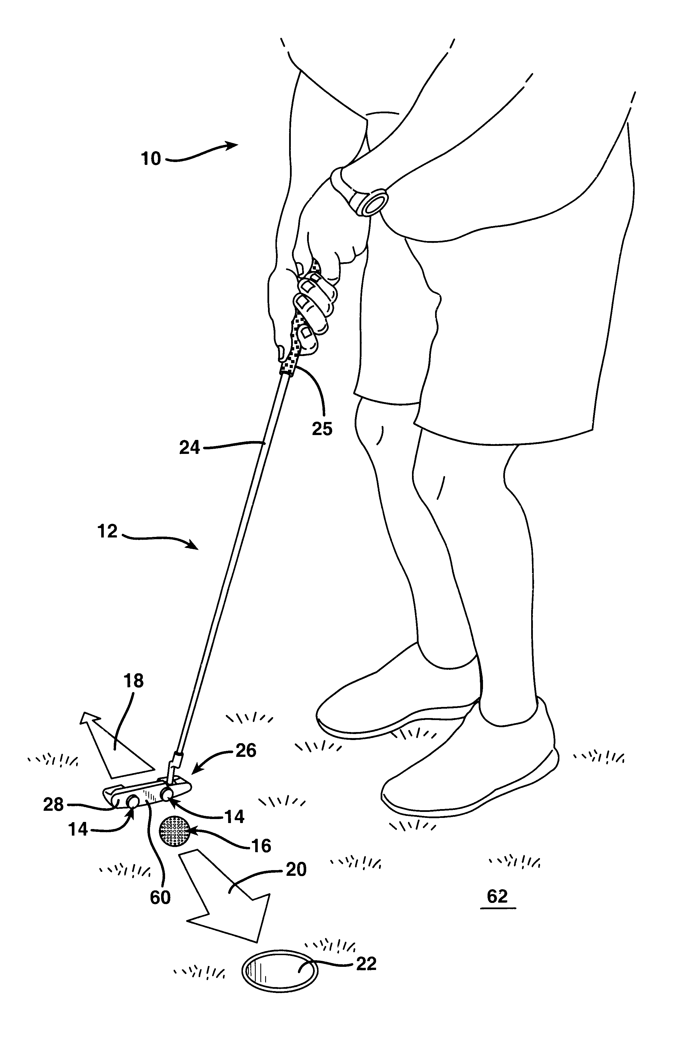
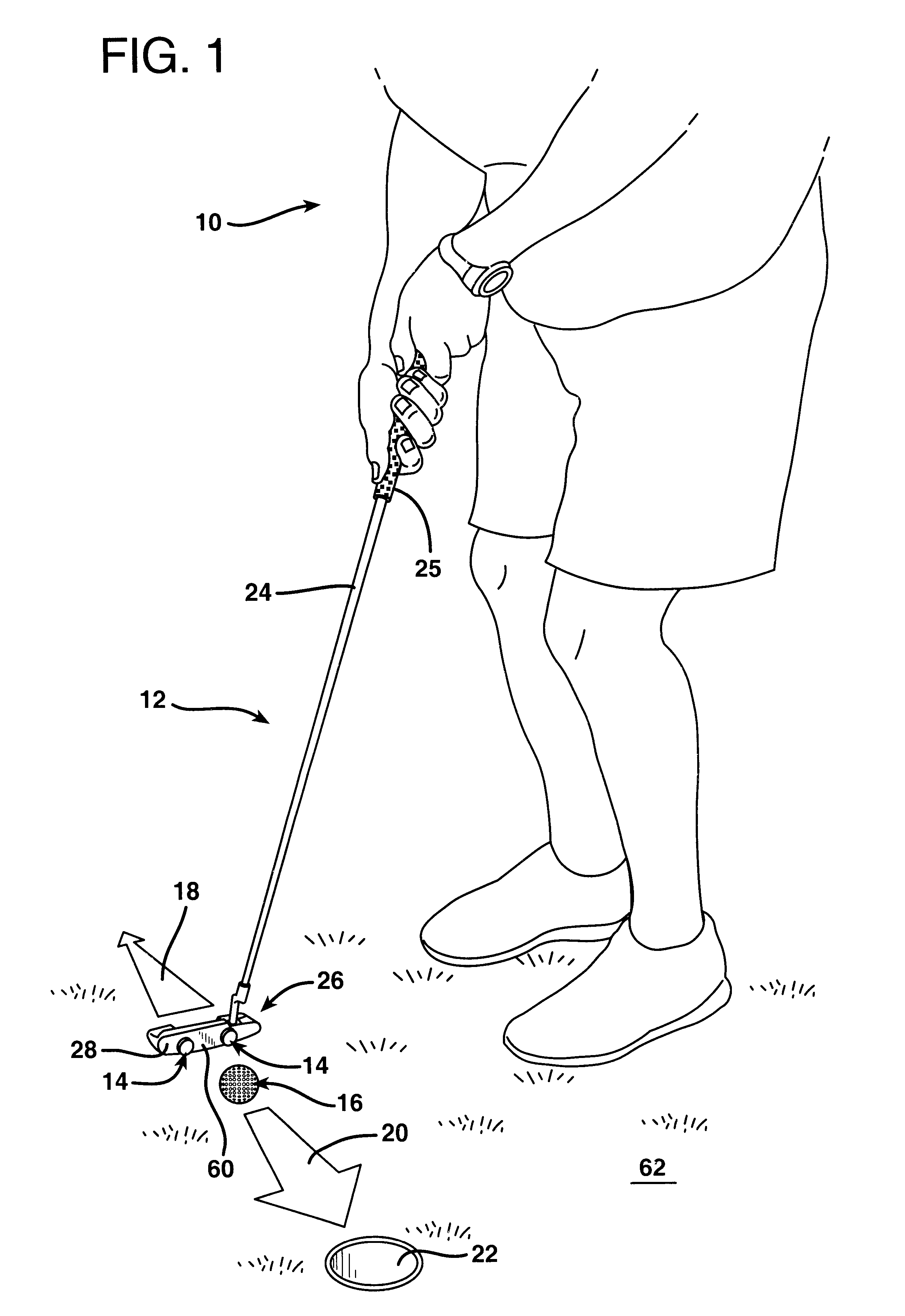
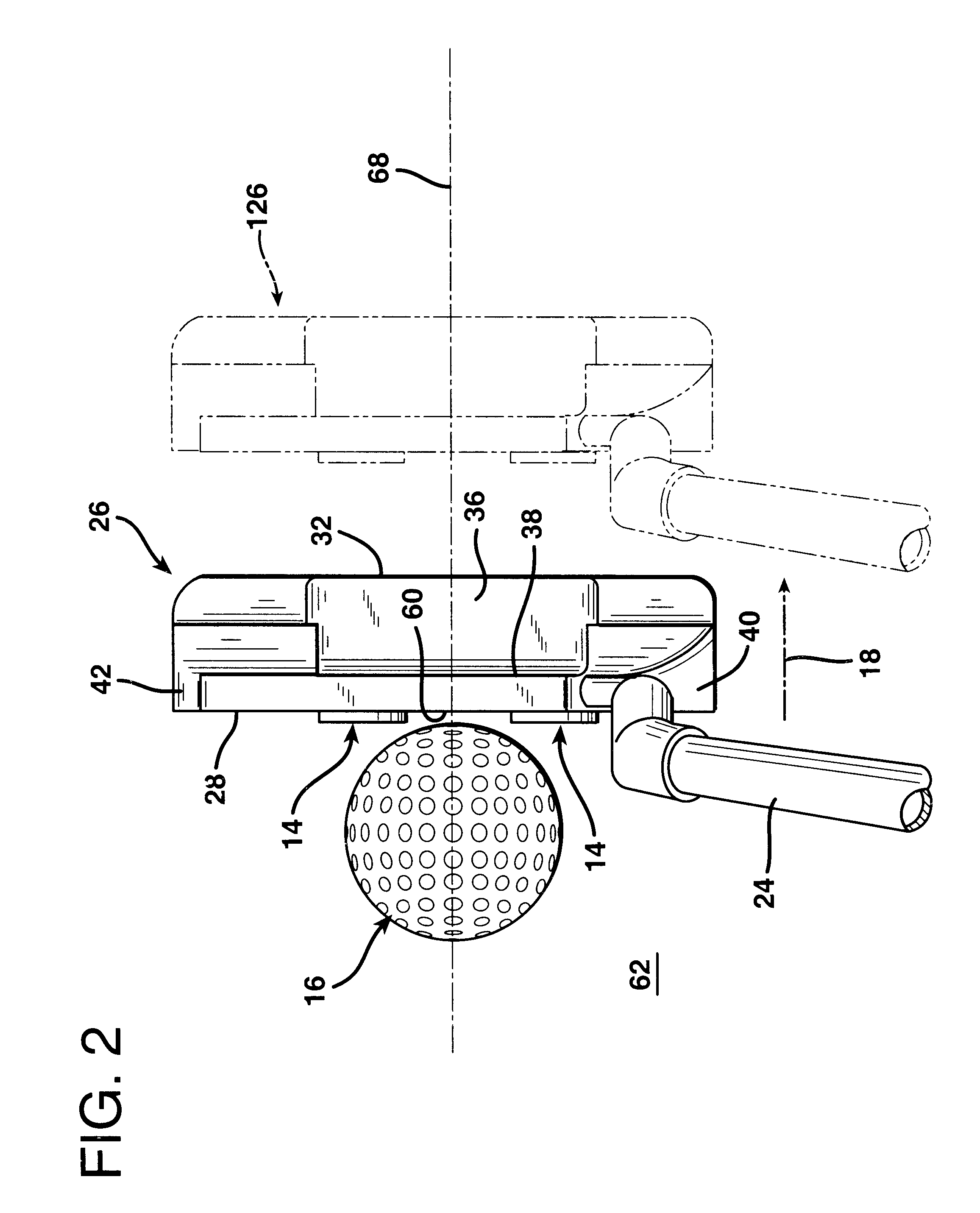
FIG. 1 illustrates a golfer indicated generally at 10 utilizing a golf putter 12 in combination with a pair of identical golf ball markers 14 according to the invention as a practice aid for golf putting. The golfer 10 first places the golf ball markers 14 on the ball impact face 28 of the golf putter head 26. The ball markers 14 are each located off-center on the ball-impact face 28, one closer to the heel 40 and the other closer to the toe 42. The golfer 10 then observes the alignment of the golf ball markers 14 relative to a golf ball 16 while moving the golf putter 12 in a backstroke, indicated by the directional arrow 18, and then forwardly in an actual putting stroke and follow through, as indicated by the directional arrow 20. By utilizing the golf ball markers 14 for purposes of alignment in combination with the golf putter 12, the golfer 10 is able to more precisely execute a proper backstroke 18 and putting stroke and follow through 20 so that the golf ball 16 will drop in...


PUM


Abstract

At least one, and preferably a pair, of golf ball markers with magnets incorporated therein are employed in combination with a golf putter as a putting training aid. The golf ball markers may be placed a short distance apart on the ball-impact impact face of the putter for a golfer to practice putting. If the golfer correctly brings the putter face into contact with the ball, the ball will be impacted by the center of the face directly between the two magnetized ball markers. If the golfer's putting stroke is not correct, one or the other of the ball markers will strike the ball, thereby creating a tactile sensation transmitted through the putter shaft that informs the golfer of the error in execution of the putting stroke. Magnetic golf ball markers may also be used in combination with a putter in other ways to develop a putting stroke that is consistently correct. The golfer places two of the golf ball markers with magnets incorporated therein on a golf putting practice surface. One of these markers is placed directly in front of the golf ball and one directly behind it. On the backswing, the magnetic golf ball marker behind the golf ball will spring up onto the sole of the putter head with an audible click if the putter head remains near the golf putting practice surface during the backstroke. As the putting stroke is executed, and with a proper follow through, the ball marker in front of the golf ball will be magnetically attracted to the sole of the putter head if the putter head remains near the golf putting practice surface.

Description

1. Field of the InventionThe present invention relates to the combination of a golf ball marker which incorporates a permanent magnet in its structure with a golf putter having a club head formed of a material attracted by magnetism and -the use of that combination as an aid for golf putting practice.2. Description of the Prior ArtDuring a round of golf quite frequently a golfer will arrive at a green in preparation for a golf putt, but will sometimes have to wait for several minutes for other golfers to complete their shots. During this time the golfer can contemplate the best way to execute the golf putt that is required to maximize the likelihood that the golfer's next putt will drop in the hole. In this connection it is often useful for the golfer to practice a proper putting stance, manner of addressing the ball, and swing of the golf putter club.Many golfers have difficulty putting because the line of movement of the golf putter during the putting stroke is not precisely perpe...

Claims


Application Information

Patent Timeline
IPC IPC(8): A63B57/00A63B53/04A63B69/36
CPCA63B69/3676A63B69/3617A63B69/3685A63B2053/0458A63B2209/10A63B63/00A63B2071/0694A63B2053/0441A63B53/0441A63B53/0458
Inventor TATE, JOHN R.
Owner TATE JOHN R
Why Eureka
Try Eureka