Gas chromatograph sample and column-switching valve

a technology of gas chromatograph and column switch, which is applied in the direction of diaphragm valve, engine diaphragm, instruments, etc., can solve the problems of reducing the room in the oven for additional columns and detectors, and not providing internal blockage of fluid communication between one or more pairs of ports

Inactive Publication Date: 2002-09-24
SIEMENS AG +1
View PDF10 Cites 56 Cited by
  • Summary
  • Abstract
  • Description
  • Claims
  • Application Information

AI Technical Summary

Problems solved by technology

Prior art sample and column switching valves usually includes a multiplicity of ports but do not provide internal blocking of fluid communication between one or more pairs of ports.
Blocking the port or ports would not accomplish that result as the port or ports are then blocked for both

Method used


Image

  • Gas chromatograph sample and column-switching valve
  • Gas chromatograph sample and column-switching valve
  • Gas chromatograph sample and column-switching valve

Examples


Embodiment Construction

)

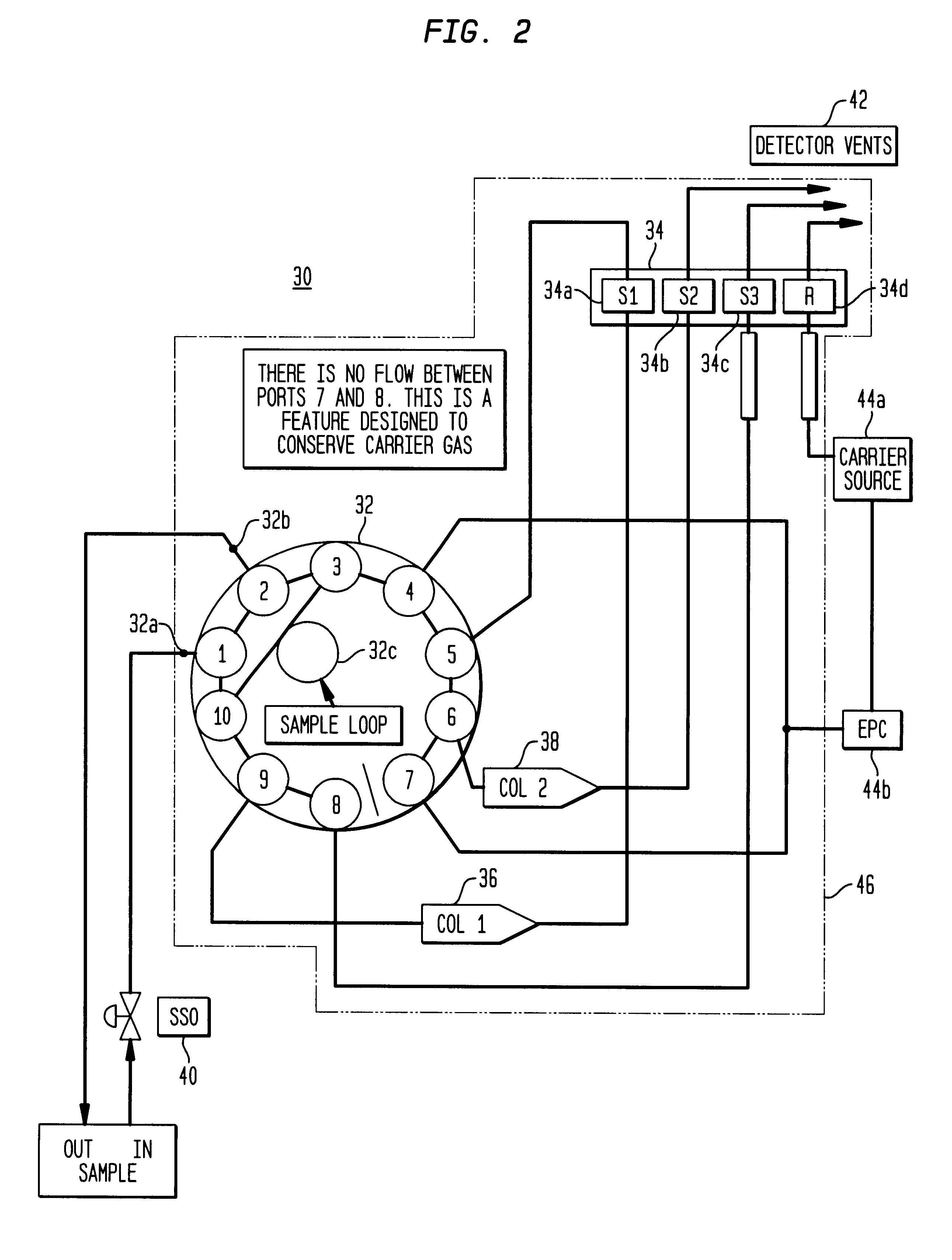
Referring now to FIG. 2, there is shown a schematic diagram for using the valve 32 of the present invention in a GC 30 that has a multi-cell detector 34. GC 30 also has first and second columns 36 and 38, sample shutoff valve (SSO) 40, detector vents 42, a carrier source 44a, an electronic pressure control (EPC) 44b which is used to bring the carrier gas into the GC and an oven 46 which is shown in FIG. 2 by the dashed box. The heater typically included in oven 46 has been omitted from FIG. 2 for ease of illustration. The valve 32, multi-cell detector 34, and first and second columns 36 and 38 are in the oven 46.

Multi-cell detector 34 includes a first sensor (S1) 34a, a second sensor (S2) 34b, and a third sensor (S3) 34c and a reference (R) 34d.

Referring now to FIG. 3a, this figure illustrates a simplified flow diagram showing how the carrier gas flows through valve 32, columns 36 and 38 and multi-cell detector 34 to detector vents 42 when the valve 32 is in the ON position. As can...


PUM


Abstract

A multiport, diaphragm sealed valve suitable for use as both a sampling and column switching valve. The valve is constructed to internally block fluid communication between one or more pairs of ports in a valve operating mode. Such blocking may be used to conserve carrier gas when the valve is in the ON position.

Description

This invention relates to valves used in gas chromatographs ("GC") and more particularly to such a valve that internally blocks fluid communication between ports.DESCRIPTION OF THE PRIOR ARTAll process GCs include a sample valve. The function of such a valve is to collect a precise volume of a liquid or vapor sample. The components of the collected sample are then separated by the one or more columns in the GC based on some physical or chemical property. The one or more detectors inside the GC are used to sense the separated components as they leave the end of the one or more columns so that component concentrations can be determined.Referring to FIG. 1 there is shown a simplified block diagram of an on-line process GC 10. GC 10 has a sample extraction and conditioning system 12 which is used to remove a sample from process stream 14. The sample is conditioned to filter contaminants out of the sample before it enters sample valve 16 through sample input port 16a. The valve 16 has al...

Claims


Application Information

Patent Timeline
IPC IPC(8): F16K11/02G01N30/00G01N30/20G01N30/02
CPCF16K11/022G01N30/20G01N2030/025G01N2030/201Y10T137/87716Y10T137/87893Y10T137/87764
Inventor DAHLGREN, ROBERT W.BADE, ROBERT K.HUNT, STEPHEN B.
Owner SIEMENS AG
Why Eureka
Try Eureka