
Fluid injector with vent/proportioner ports

a technology of fluid injector and venting port, which is applied in the direction of machines/engines, liquid displacement, separation processes, etc., can solve the problems of increasing the cost of the device, requiring frequent maintenance for the unit to operate properly, and prone to wear and mechanical failur

Inactive Publication Date: 2002-09-24
E Z FLO INJECTION SYST
View PDF11 Cites 12 Cited by
  • Summary
  • Abstract
  • Description
  • Claims
  • Application Information

AI Technical Summary

Problems solved by technology

There are a number of problems encountered with each type of equipment available in delivering an accurately proportioned injection amount.
The components of this type of system are mechanical and electronic so they are subject to wear and mechanical failure.
The seals require frequent maintenance for the unit to operate properly.
This design is limited in the amount of fluid flow it can operate with and as flows increase, the cost of the device increases.
They require high pressure to operate and the high restriction in the fluid stream greatly reduces the fluid stream volume.
Fluctuations in pressure can cause the device to not inject continuously creating uneven distribution.
They are also unable to dependably inject solutions such as water-soluble fertilizers without plugging.
Venturi systems generally have relatively small flow orifices and the fertilizer solution has a tendency to settle, creating sedimentation that plugs these orifices.
This method doesn't control the amount being distributed and can give unreliable distribution.
If the air is not removed from the system, a potentially hazardous condition exists in that air compresses under pressure, which creates a higher stress on the storage tank than fluids under pressure and can cause the storage tank to rupture at much lower operating pressures.
This limits the fluid available to mix with soluble products to make them an injectable solution, causing the system to not inject accurately or possibly not inject at all due to plugged flow ports.
Also, this design does not provide a means of injecting more than one solution from the same tank at independent ratios.
While it does evacuate the air from the tank automatically, it is mechanical in nature so it is subject to wear and eventual failure.
It does not provide back flow protection, establish proportioning rates or allow air to be vented through the piping system.
It also does not provide a means of injecting more than one solution from the storage tank at independent ratios.
This creates a high restriction in the flow line, significantly reducing flow volume and pressure.
This design cannot operate at low pressures or automatically mix dry products and keep them an injectable solution.
It does not provide for the injection of liquids into a flow line, only the mixing of incoming flows.

Method used


Image

  • Fluid injector with vent/proportioner ports
  • Fluid injector with vent/proportioner ports
  • Fluid injector with vent/proportioner ports

Examples


embodiment

FIG. 4--Additional Embodiment

An additional embodiment is shown in FIG. 4. It shows the addition of bladder 16a and 16b. Bladder 16a is connected to vent / proportioner port 4a that is connected to tank outlet port 4. Bladder 16b is connected to vent / proportioner port 4b that is connected to tank outlet port 4. Fill port 17a is connected to bladder 16a. Fill port 17b is connected to bladder 16b. Fill port 17c is connected to storage tank 13. Drain valve 18 is connected to storage tank 13. Fill port valve 19a is connected to fill port 17a. Fill port valve 19b is connected to fill port 17b. Fill port valve 19c is connected to fill port 17c.

FIG. 4--Operations

The method of using the fluid injector with vent / proportioner ports as shown in FIG. 4 is to turn off all flow in fluid flow line 1. Relieve system pressure by opening a valve downstream in the fluid flow line 1. When the pressure is relieved, close the valve. Drain all fluid from storage tank 13 by opening drain valve 18 and fill por...


PUM

PropertyMeasurementUnit
Flow rateaaaaaaaaaa
Solutionaaaaaaaaaa
Injection velocityaaaaaaaaaa

Abstract

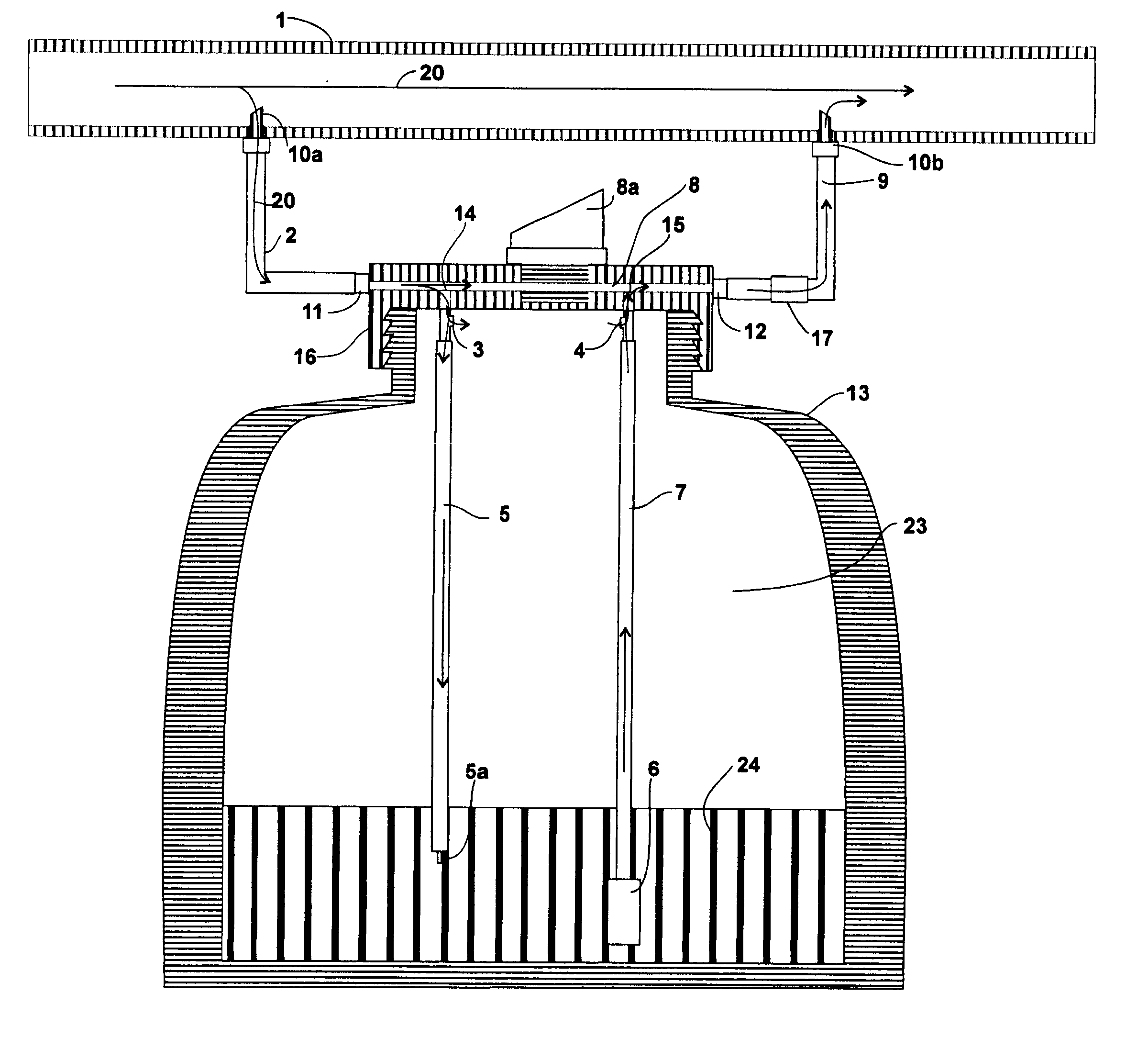
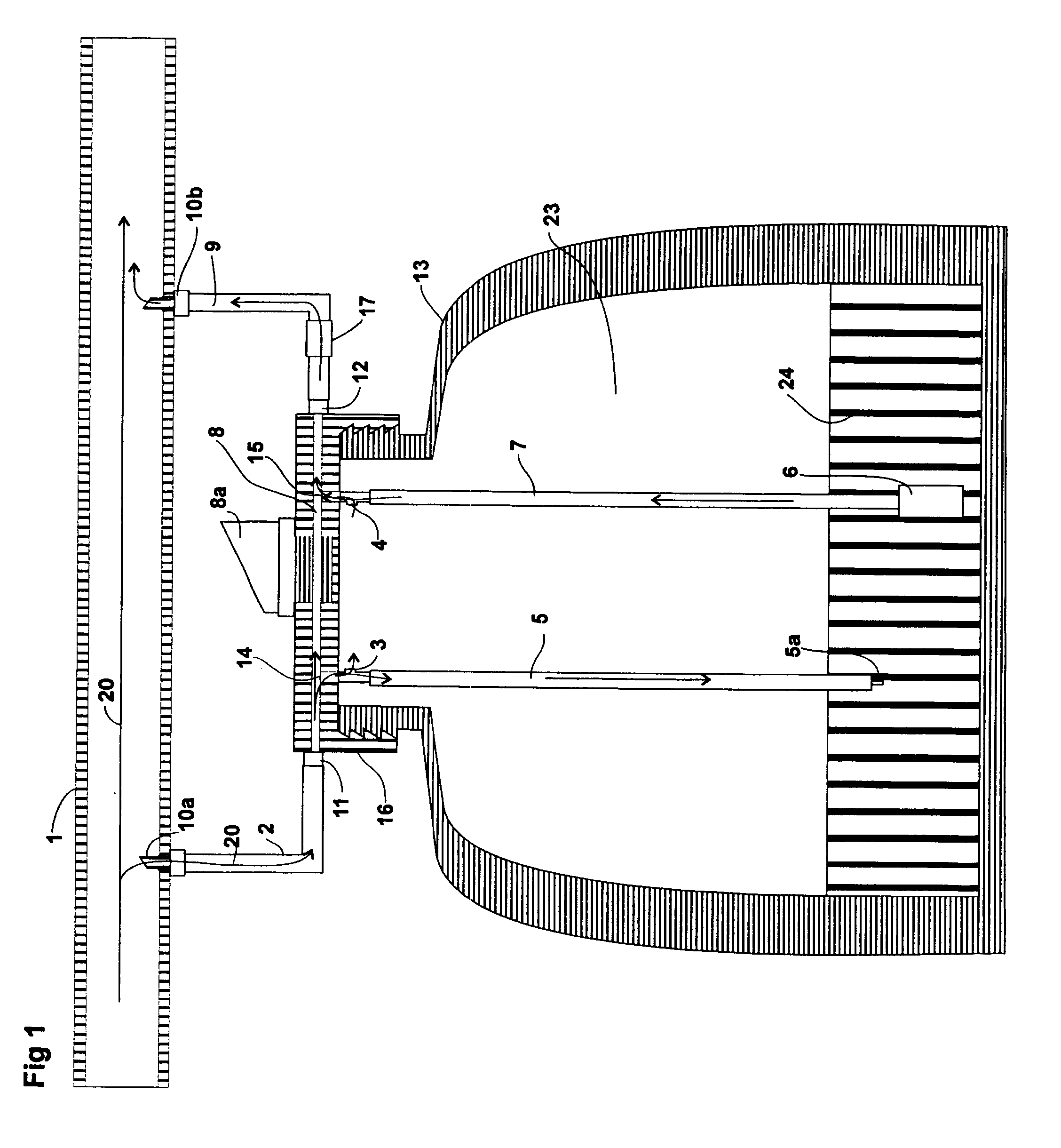
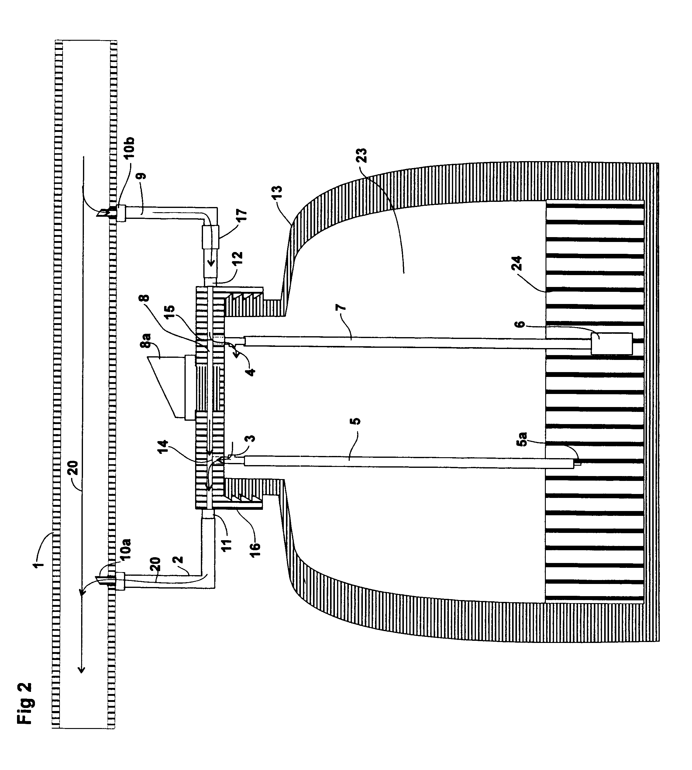
A fluid injector made of pressure rated components that attach to a fluid flow line so that flow is transferred from the flow line, into the injection unit and back to the fluid flow line. The inlet flow is used to pressurize the storage tank and provide a solution to mix with injection solutions in the tank to provide an accurate preset or adjustable injection rate into the fluid flow line. Vent / proportioner ports provide back flow protection, prevent fluid from siphoning from the storage tank, provide an internal air release port and set injection ratios. A mixing control valve adjusts the injection ratios by mixing outgoing injection solutions with incoming fluid from the fluid flow line. Flexible bladders isolate one or more injection solutions within one storage container which are injected simultaneously at independent injection rates.

Description

Not applicable.BACKGROUND--FIELD OF INVENTIONThis invention relates to storage tanks and fluid injection systems, specifically to injection metering devices.BACKGROUND--DESCRIPTION OF PRIOR ARTA variety of means have been used to inject fluids into fluid streams. These include metering pumps, water powered pumps, siphon devices, flow through devices and gravity feed drainage equipment.There are a number of problems encountered with each type of equipment available in delivering an accurately proportioned injection amount. Metering pumps are either set to inject a predetermined amount into a fluid stream without a means of adjusting to changes in flow volume in the fluid stream, or they are controlled electronically by flow sensors located in the fluid stream. The components of this type of system are mechanical and electronic so they are subject to wear and mechanical failure. Water powered pumps adjust automatically to changes in flow in the fluid stream but are a mechanical device...

Claims


Application Information

Patent Timeline
IPC IPC(8): B01F5/04F04F5/24F04F1/00F04F1/06F04F5/00B01F15/04B01F3/08B05B7/24
CPCB01F5/0495B01F5/0496B05B7/2445F04F1/06F04F5/24B01F3/08B01F15/04Y10T137/3112Y10T137/8597Y10T137/0318Y10T137/4891B01F23/40B01F25/315B01F25/316B01F35/80Y02P60/21
Inventor GILMORE, DAN
Owner E Z FLO INJECTION SYST
Learn More