
Clothesline system with a support system and improved clothespins

Inactive Publication Date: 2002-09-24
LE GRP DSD
View PDF38 Cites 12 Cited by
  • Summary
  • Abstract
  • Description
  • Claims
  • Application Information

AI Technical Summary

Benefits of technology

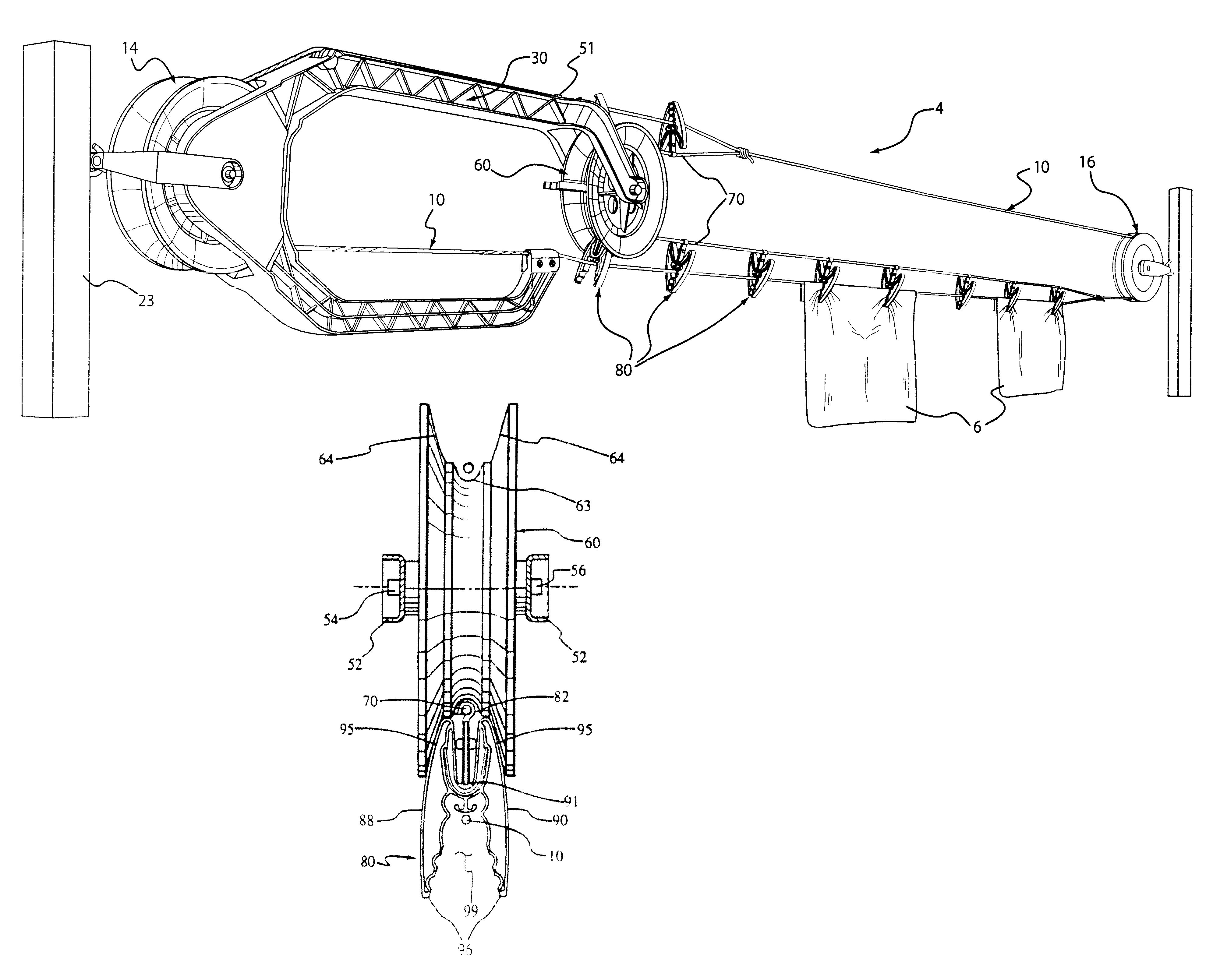
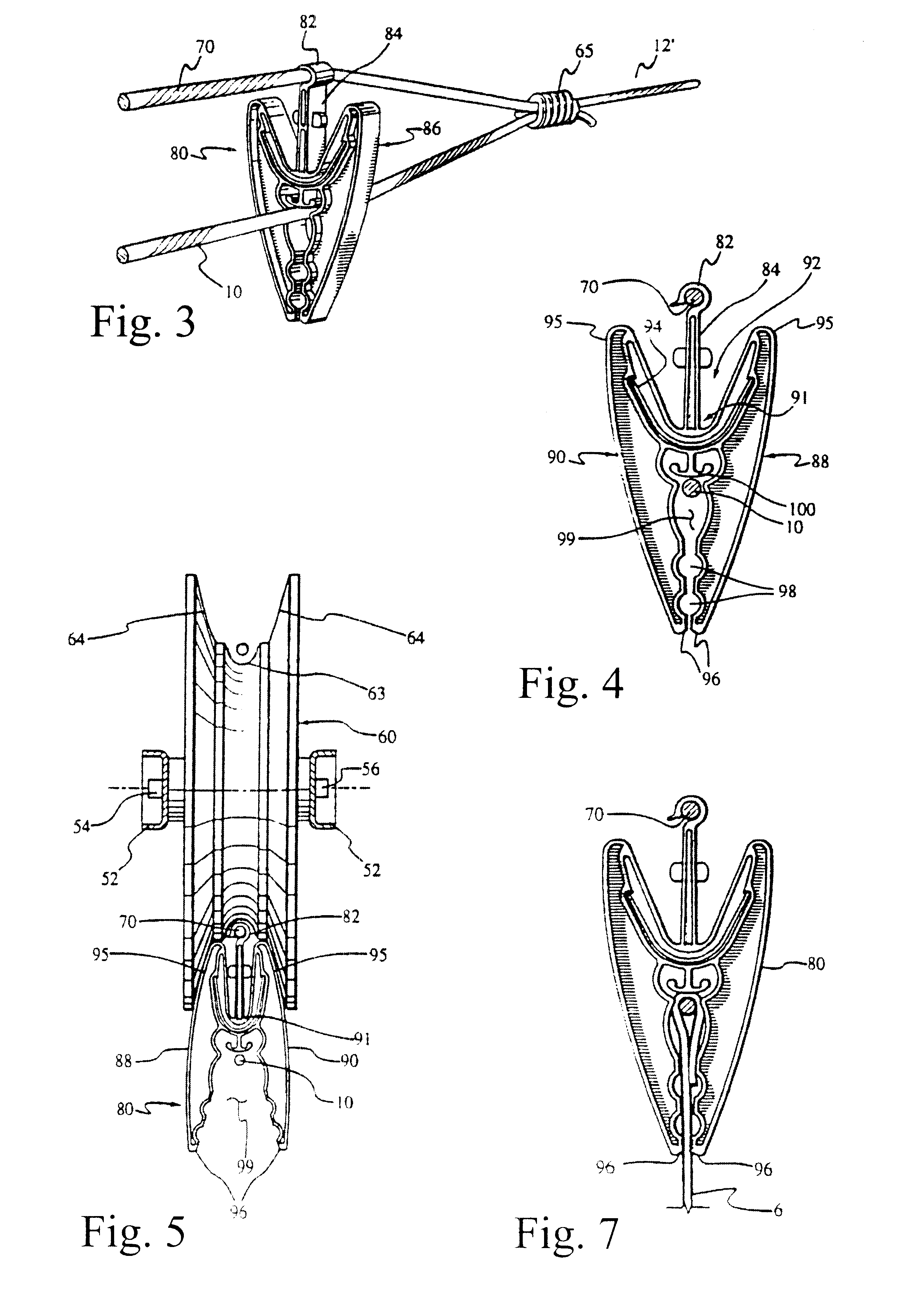
As best illustrated in FIGS. 3 and 4, each clothespin 80 comprises three parts, namely, a head 82, a neck 84 and a body 86. Head 82 is a hook configured member that can be frictionally attached onto the secondary cable 70. The head is resilient so it can be readily detached from the secondary cable 70 if desired. The ability to readily remove and install the head is convenient because the clothespins 80 may be installed after the clothesline system has been assembled. This also allows to place a desired number of clothespins 80 anywhere along the secondary cable, contrary to the system disclosed in the previously referred patent where the pins are not removable. The neck 84 is a linear member that connects head 82 with body 86 so as to support the latter on the secondary cable 70. The body 86 is a flat jaw like member having two legs 88 and 90 that are pivotally connected by a hinge area 91. The hinge area defines a cavity 92 around neck 84 that extends from one leg to the other. A C-shaped spring biasing member 94-urges legs 88 and 90 to cl

Problems solved by technology

Although the system facilitates securing the clothes onto the clothesline system, it fails to provide a means for preventing the main cable from sagging beyond an acceptable range within which the pins can engage the cable and secure the clothes that are placed to dry.
Moreover, the clothespins described in this reference are designed with only one clothes holding position, thus limiting the range within which the clothes cable may sag away from the secondary cable.

Method used


Image

  • Clothesline system with a support system and improved clothespins
  • Clothesline system with a support system and improved clothespins
  • Clothesline system with a support system and improved clothespins

Examples


Embodiment Construction

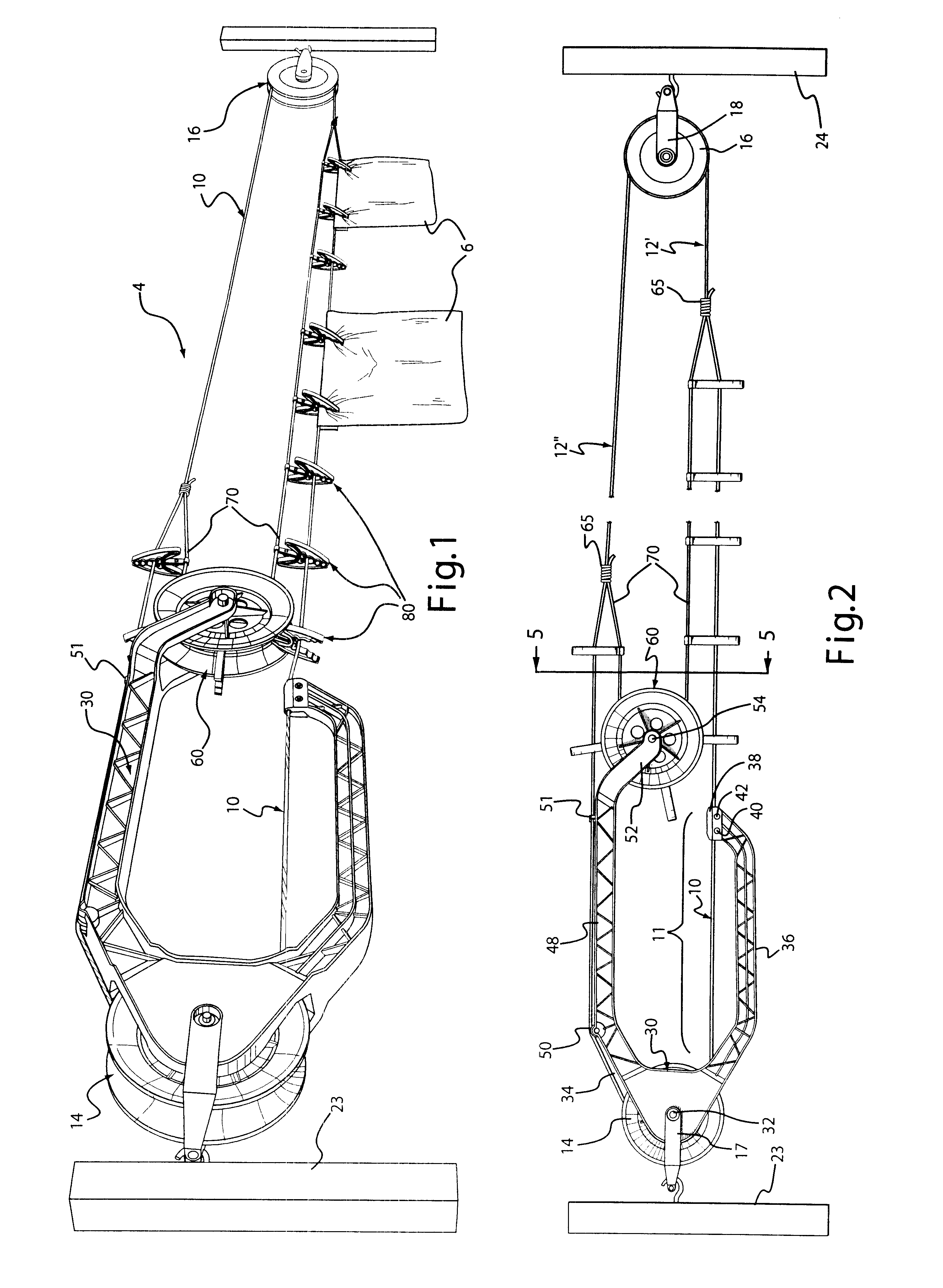
Referring now to the drawings, FIG. 1 illustrates a clothesline system 4 on which articles of clothing 6 are placed to dry. Broadly stated, the clothesline includes a main cable 10 supported between two spaced apart pulleys 14 and 16 and a support member 30 to which pulley 14 is mounted. A pin lay wheel 60, also mounted to the support member 30, is provided to deposit clothespin 80, which are attached to a secondary cable 70, onto articles of clothing 6 that may be placed on the main cable 10.

The main cable 10 is a continuous cable whose ends are attached to establish two continuous runs between pulleys 14 and 16, namely a lower run 12' and an upper run 12". Pulley 14 is rotatably mounted to support member 30 which in turn is attached to a bracket 17 that is pivotally attached to a support structure 23. Pulley 16 is rotatably mounted to bracket 18 that is pivotally attached to support structure 24 that is at a spaced apart distance from support structure 23.

As best seen in FIG. 2, t...


PUM


Abstract

A clothesline system is provided for automatically applying clothespins to articles to be dried once they are placed on a clothesline. The clothesline system comprises first and second pulleys, which are positioned at a spaced apart distance from each other, as well as a main cable, a secondary cable and a plurality of clothespins. The clothespins are capable of being removably attached to the secondary cable, and are movable between an open and closed position for receiving and gripping articles to be dried to the main cable. The clothesline system further comprises a mechanism for automatically opening and closing the clothespins so that they are able to either selectively grip or release the articles to be dried. Finally, the clothesline system comprises a support system for guiding and supporting the main cable such that the main cable is prevented from sagging beyond an acceptable distance within which the clothespins are capable of being attached to the main cable.

Description

The present invention relates to a clothesline system that can automatically secure clothes onto a main clothes cable without having to manually do so with clothespins. A distinguishing feature of the clothesline system resides in the provision of a support member that prevents the main cable from sagging beyond a predetermined distance from a secondary cable while under the effect of the clothes weight. The secondary clothes cable comprises improved clothespins that can be used wit the clothesline system to engage the main cable and that feature multiple clothes holding positions. The invention also extends to a cable connector element that allows one section of a continuous cable to form the main cable and a second section of the continuous cable to form the secondary cable. As a result, the main cable is continuous with the secondary cable.Typical clothesline systems provide a support on which wet clothes are placed to dry. The clothesline system includes a continuous cable that ...

Claims


Application Information

Patent Timeline
IPC IPC(8): D06F53/00
CPCD06F53/00Y10T24/39
Inventor DOYLE, NOELDOYLE, STEVEN
Owner LE GRP DSD
Learn More