Eureka AIR delivers breakthrough ideas for toughest innovation challenges, trusted by R&D personnel around the world.

Television system discriminator and television system discrimination method

Inactive Publication Date: 2002-09-24
HANGER SOLUTIONS LLC
View PDF3 Cites 1 Cited by
  • Summary
  • Abstract
  • Description
  • Claims
  • Application Information

AI Technical Summary

Benefits of technology

to provide a television system discriminator that can be applied when a TV input signal is an analog signal or a digital signal and that is capable of accurately discriminating between television systems where the difference between the line number and the field number is small.

Problems solved by technology

However, there is the fear that it will be difficult for the aforementioned television system discrimination circuit to make discriminations or that the precision of such discriminations will be extremely low when the difference between the line number and field number is small as between two types of TV systems taken as objects of discrimination.
In both cases the difference in the number of fields per second is extremely small and discrimination is therefore difficult using the TV system discriminator 2 shown in FIG. 2.
However, this discrimination method employing this PLL circuit cannot be applied to cases where the TV input signal is already in the form of a digital signal.

Method used


Image

  • Television system discriminator and television system discrimination method
  • Television system discriminator and television system discrimination method
  • Television system discriminator and television system discrimination method

Examples


Embodiment Construction

The following is a description of an embodiment of a TV system discriminator to which this invention is applied.

The TV system discriminator shown in this specific embodiment is capable of discriminating between television systems of difference field numbers per unit time (field frequency).

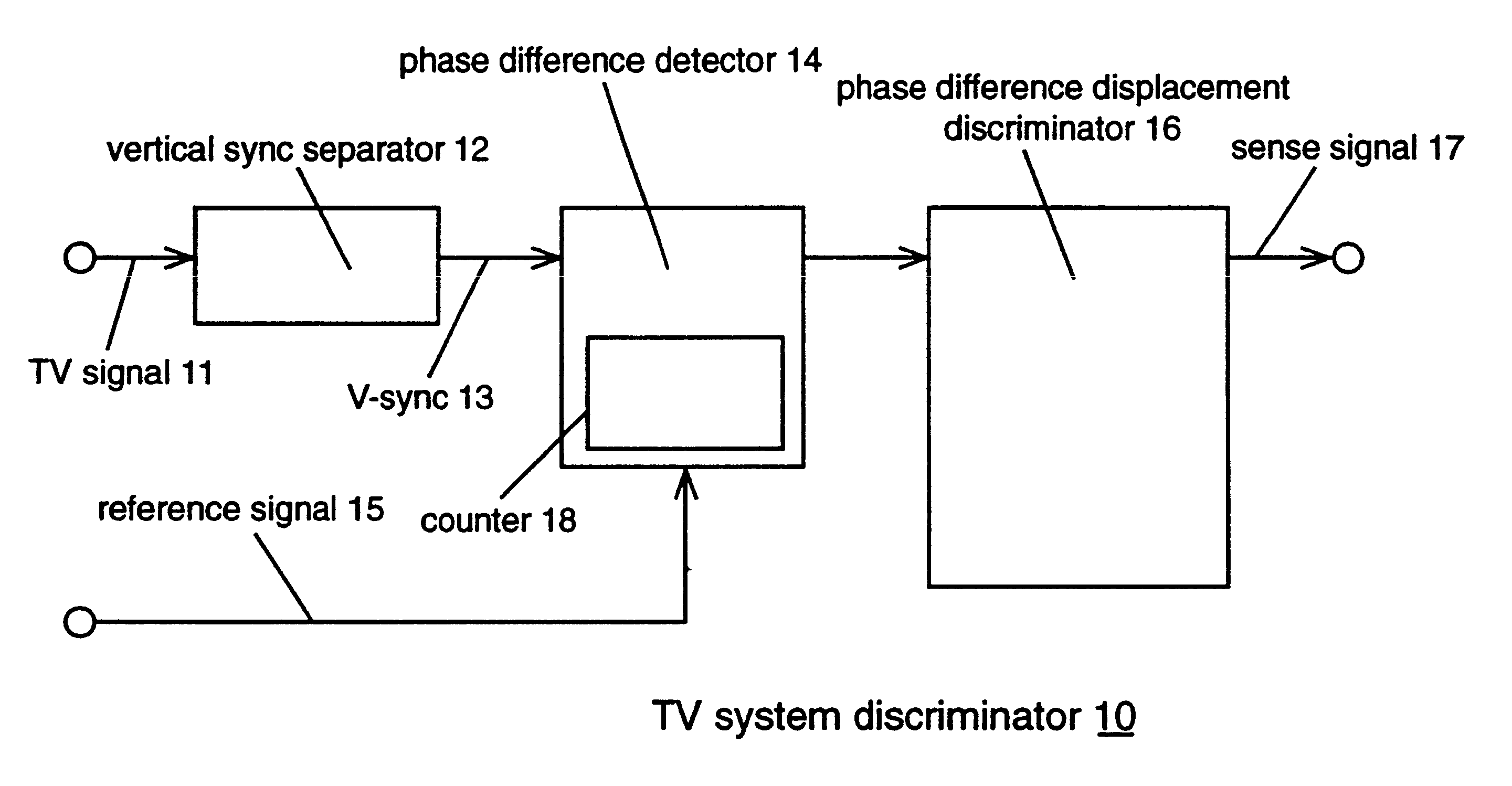
FIG. 3 is a block diagram showing a configuration of a TV system discriminator 10 of this embodiment.

This TV system discriminator 10 comprises a vertical sync separator 12, phase difference detector 14 and phase difference displacement discriminator 16.

The vertical sync separator 12 is for separating a V-sync 13 constituting a synchronized signal from a TV input signal 11 consisting of a composite TV signal, a luminance signal and a color signal or chroma signal. This separated V-sync is then inputted to the phase difference detector 14.

As shown in FIG. 4, an externally supplied reference signal V-sync 15 having the same field frequency as a vertical sync signal of a prescribed television system is...


PUM


Abstract

The object of the present invention is to provide a TV system discriminator capable of being applied to when the inputted TV signal is an analog signal or a digital signal, and capable of accurately discriminating between TV systems with small differences in line number and field number.In order to achieve the above object, the TV system discriminator of the present invention comprises a separator for extracting a synchronized signal for a TV signal inputted in accordance with one of a plurality of TV systems, a phase difference sensor for sensing a phase difference of this separated synchronized signal and a prescribed reference signal, and a phase difference displacement discriminator for discriminating a TV system corresponding to an inputted TV signal based on the direction of temporal displacement of this phase difference.

Description

1. Field of the InventionThe present invention relates to a TV system discriminator for automatically discriminating a TV (television) system corresponding to an inputted TV signal. This circuit employs, for example, a television signal converter.2. Description of Related ArtAs shown in a block diagram of FIG. 1, a typical TV system converter 1 is equipped with a TV system discriminator 2 for automatically discriminating a TV system (for example, the NTSC system or the PAL system) corresponding to a TV signal inputted at an input stage.When the television system discriminated by the TV system discriminator 2 coincides with the television system according to a signal to be outputted from the TV system converter 1 the TV system converter 1, does not change the designation of television system. When the discriminated television system differs from the television system to be outputted from the TV system converter 1, the TV system converter 1 changes over to the television system for th...

Claims


Application Information

Patent Timeline
IPC IPC(8): H04N5/46H04N11/00
CPCH04N5/46H04N11/002H04N21/42607H04N11/24
Inventor MASUYA, YUZURUYAMAUCHI, TATSUO
Owner HANGER SOLUTIONS LLC
Why Eureka
Eureka Blog
Learn More