Dual ball ramp actuator for locking differential

Inactive Publication Date: 2002-10-08
DANA AUTOMOTIVE SYST GRP LLC
View PDF16 Cites 89 Cited by
  • Summary
  • Abstract
  • Description
  • Claims
  • Application Information

AI Technical Summary

Problems solved by technology

One problem with the use of a ball ramp actuator to supply the clutch clamping force is that the mechanics of prior art unidirectional ball ramp mechanisms result in a limited sensitivity due the short travel distance of the ball and ramp assembly due to limited space.
Providing ramps at a constant radius or concentric cam path provides a limited travel path for the ball(s) and thereby limits sensitivity.
However, a vehicle that is stuck may move forward and reverse to free itself, and to

Method used


Image

  • Dual ball ramp actuator for locking differential
  • Dual ball ramp actuator for locking differential
  • Dual ball ramp actuator for locking differential

Examples


Embodiment Construction

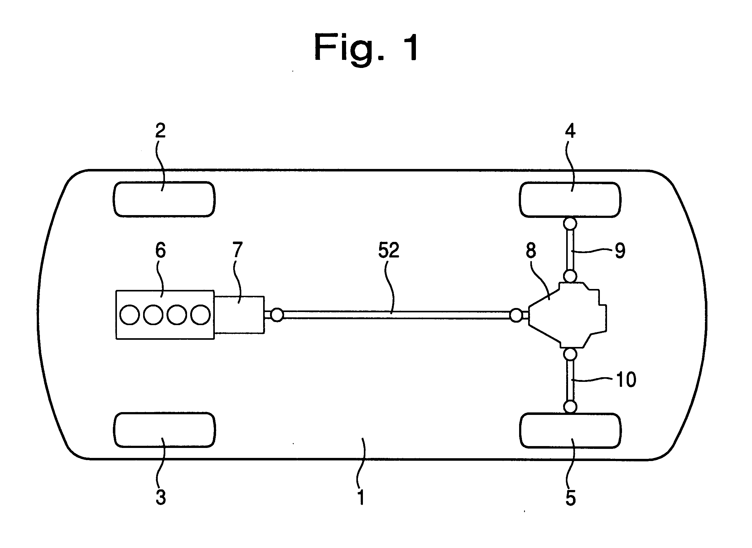
Referring now to FIG. 1 of the drawings, illustrated is in diagrammatic plan view a rear wheel drive motor vehicle 1, comprising front wheels 2, 3; rear wheels 4, 5; an engine 6; gearbox 7; a differential unit 8, and drive shafts 9, 10. In this case, however, there is a propeller shaft 52 leading from the gearbox 7 to the differential unit 8 which is of course rear mounted to drive the rear wheels.

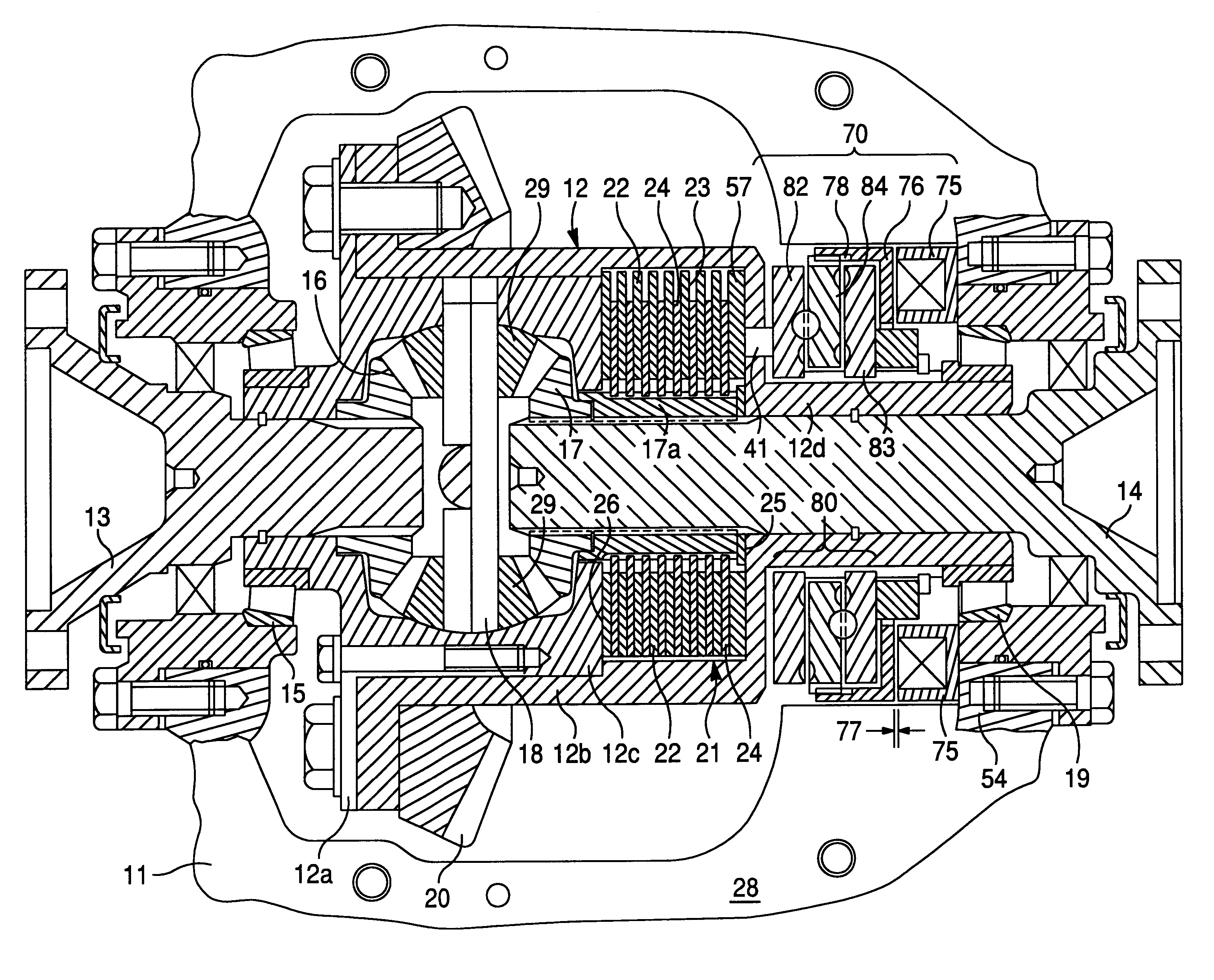
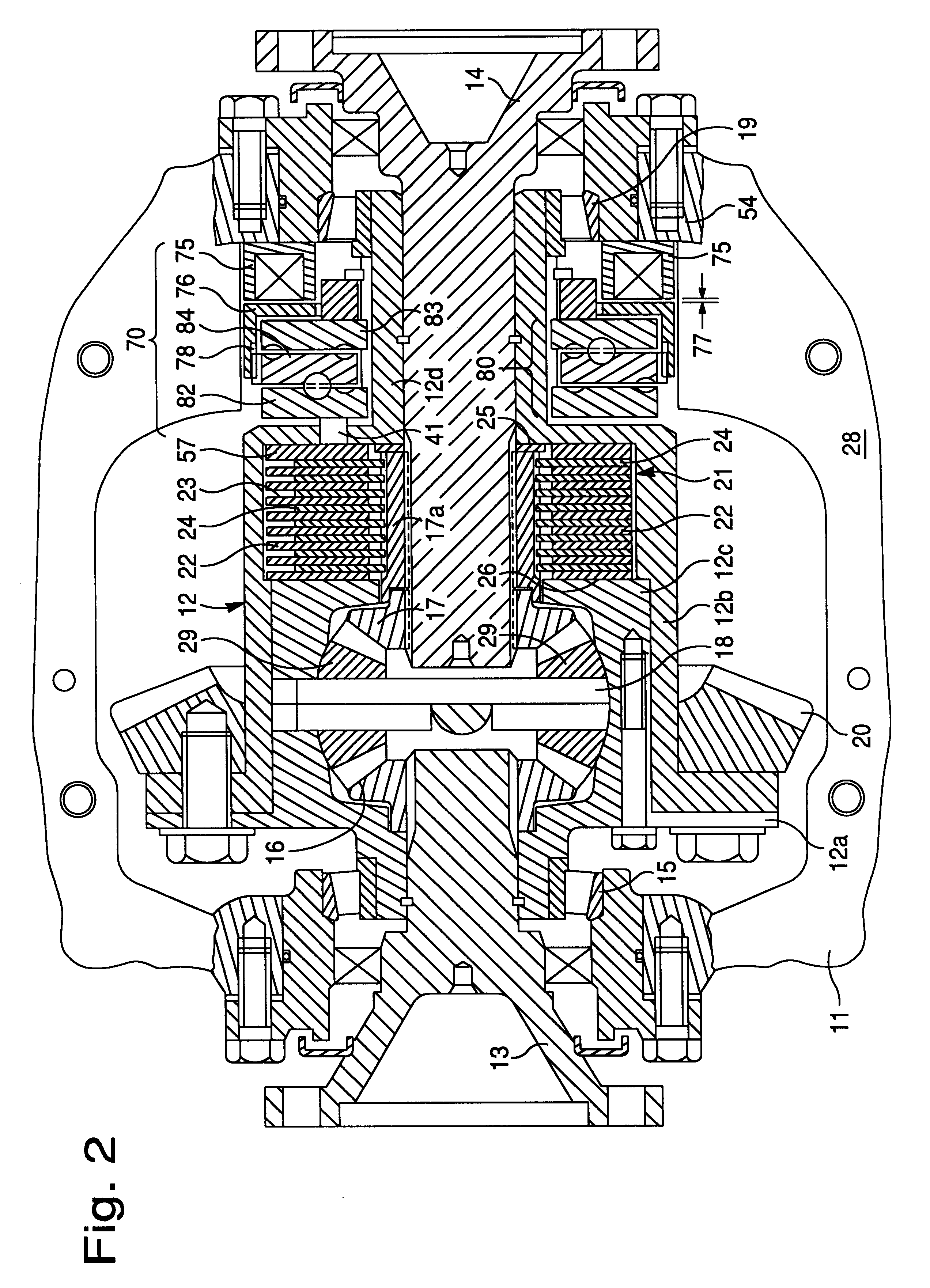
The differential unit shown in FIG. 2 comprises a housing 11 within which there is rotatably supported, by bearings 15, 19, a differential case 12. The differential case 12 has a flange to which is bolted a ring gear 20 to be engaged by a driving pinion (not shown) rotatable about an axis perpendicular to the axis of rotation of the case 12.

By way of example and explanation, the case 12 comprises three components 12a, 12b, and 12c. The component 12b is generally cup-shaped, whilst the component 12a secured to the component 12b (by the bolts which hold the ring gear 20) closes the open end ...


PUM


Abstract

A dual ball ramp actuator having a control ring acting with a pressure plates to supply an axial clutch clamping force to a differential clutch assembly where the ball ramp paths follow overlapping eccentric grooves that can be actuated in both the forward and reverse directions. The dual ramp feature doubles the effectiveness and sensitivity when compared to a single ramp system. The overlapping eccentric ball ramps increase (effectively double) the angular travel distance while reducing the ramp angle (in half). The forward and reverse feature provides clutch actuation in both the forward and reverse directions. The dual ramp, 3-piece sandwich construction permits the central control ring to roll up on two sets of balls on each side. This structure doubles the axial travel available to compress a disc pack and lock up the differential with the same ball ramp angle when compared to a single ramp system involving only two ramp plates.

Description

1. Field of the InventionThe present invention relates to a vehicle differential clutch and more particularly, to a differential clutch where friction discs are selectively engaged using a ball ramp actuator where a one-way clutch is used to provide efficient and effective clutch activation.2. Description of Related ArtDifferential clutches commonly use a series of clutch plates actuated by manual, hydraulic or electrical systems to provide various conditions of open differentials, limited slip differentials or locked-up differentials.Efforts to automate the operation of the clutch using electronics are currently underway. It is known to use an electromechanical or hydraulic actuator connected to the mechanical linkage to, in essence, replace the operator for more accurate clutch operation during slippery conditions. Using such an actuator, the mechanical linkage is moved in response to an electrical control signal generated by a central microprocessor used to process a variety of v...

Claims


Application Information

Patent Timeline
IPC IPC(8): F16D27/115F16D27/10F16D28/00F16H48/08F16H48/20F16H48/22F16H48/295F16H48/30F16H48/34
CPCF16D27/115F16H48/22F16H48/295F16H48/30F16H48/34F16D27/004F16H48/08F16H2048/204F16H2048/346
Inventor ROSCOE, CHARLES S.
Owner DANA AUTOMOTIVE SYST GRP LLC
Why Eureka
Try Eureka