
Piezo bending transducer drop-on demand print head and method of actuating it

a technology of bending transducer and drop-on-demand print head, which is applied in the direction of piezoelectric/electrostrictive devices, printing, etc., can solve the problems of high production cost of such nozzles, insufficient crosstalk reduction with these nozzles, and falsification of desired print imag

Inactive Publication Date: 2002-10-08
TALLY COMPDRUCKER
View PDF7 Cites 87 Cited by
  • Summary
  • Abstract
  • Description
  • Claims
  • Application Information

AI Technical Summary

Benefits of technology

The deflection of the neighboring piezo bending transducer by the compensating pulse effects a fluid movement locally at the nozzle assigned to the neighboring piezo bending transducer. This fluid movement acts counter to the fluid movement which is caused by the triggering pulse and the movement of the triggered piezo bending transducer directly at the nozzle assigned to the neighboring piezo bending transducer. The fluid movements fully or partly compensate for one another. No drop discharge occurs at the nozzle assigned to the neighboring piezo bending transducer (neighboring nozzle). Falsification of the print image is prevented. The disadvantageous effects of crosstalk are consequently eliminated.
In this case, the piezo bending transducer drop-on-demand print head preferably has at least three-pole piezo bending transducers, each with two piezoceramic layers, and the triggering pulses are applied by the control device to the one piezoceramic layer and the closing control pulses are applied by the control device to the other piezoceramic layer of the piezo bending transducer. In this way, the closing control pulse can also have a greater amplitude without the risk of the piezo bending transducer being destroyed, as would be the case with a monomorph.

Problems solved by technology

Furthermore, it may happen that a drop is discharged from the neighboring nozzle, which results in a falsification of the desired print image.
However, the production of such nozzles requires high expenditure.
Furthermore, the crosstalk reduction with these nozzles, while significant, is still not adequate, particularly in the case of print heads with high resolutions.
Although this leads to a complete elimination of crosstalk, it requires a substantial expenditure in production and assembly.
Furthermore, the fluid friction in the narrow gaps between piezo bending transducers and partitions leads to considerable losses in the speed of the transducer movement and in the energy of the discharged drop.

Method used


Image

  • Piezo bending transducer drop-on demand print head and method of actuating it
  • Piezo bending transducer drop-on demand print head and method of actuating it
  • Piezo bending transducer drop-on demand print head and method of actuating it

Examples


Embodiment Construction

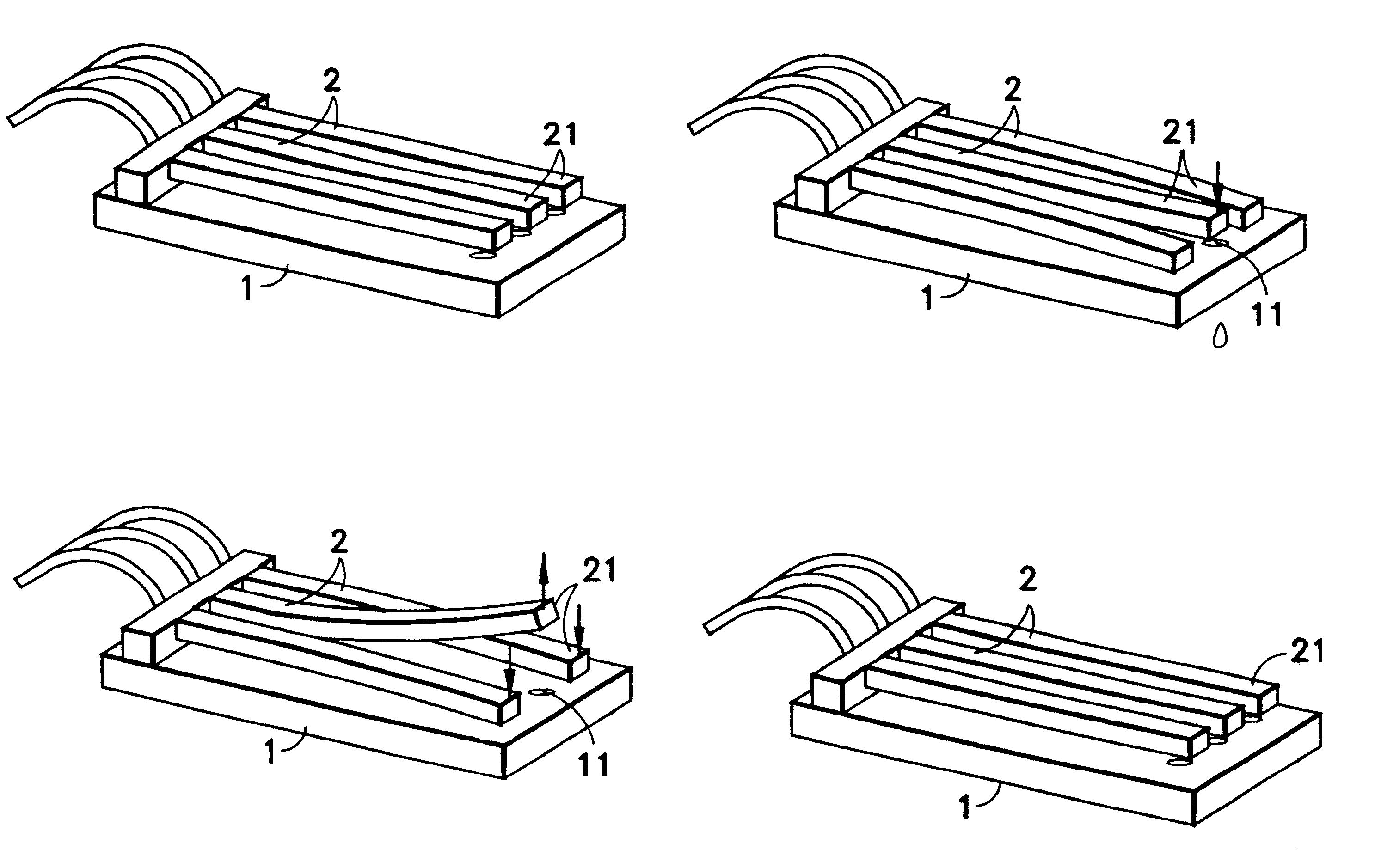
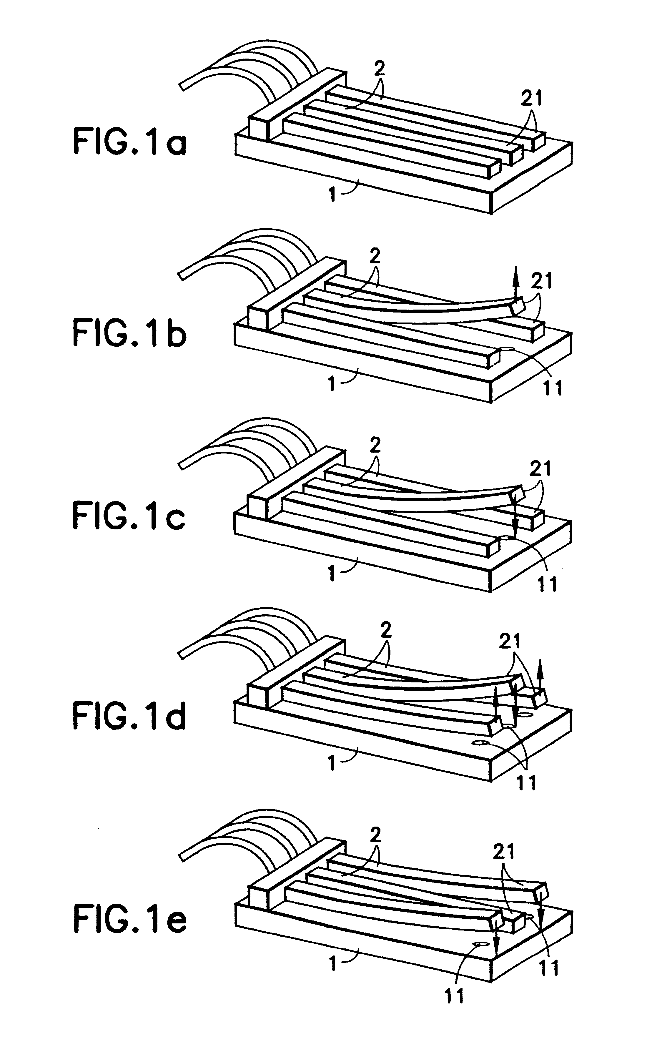
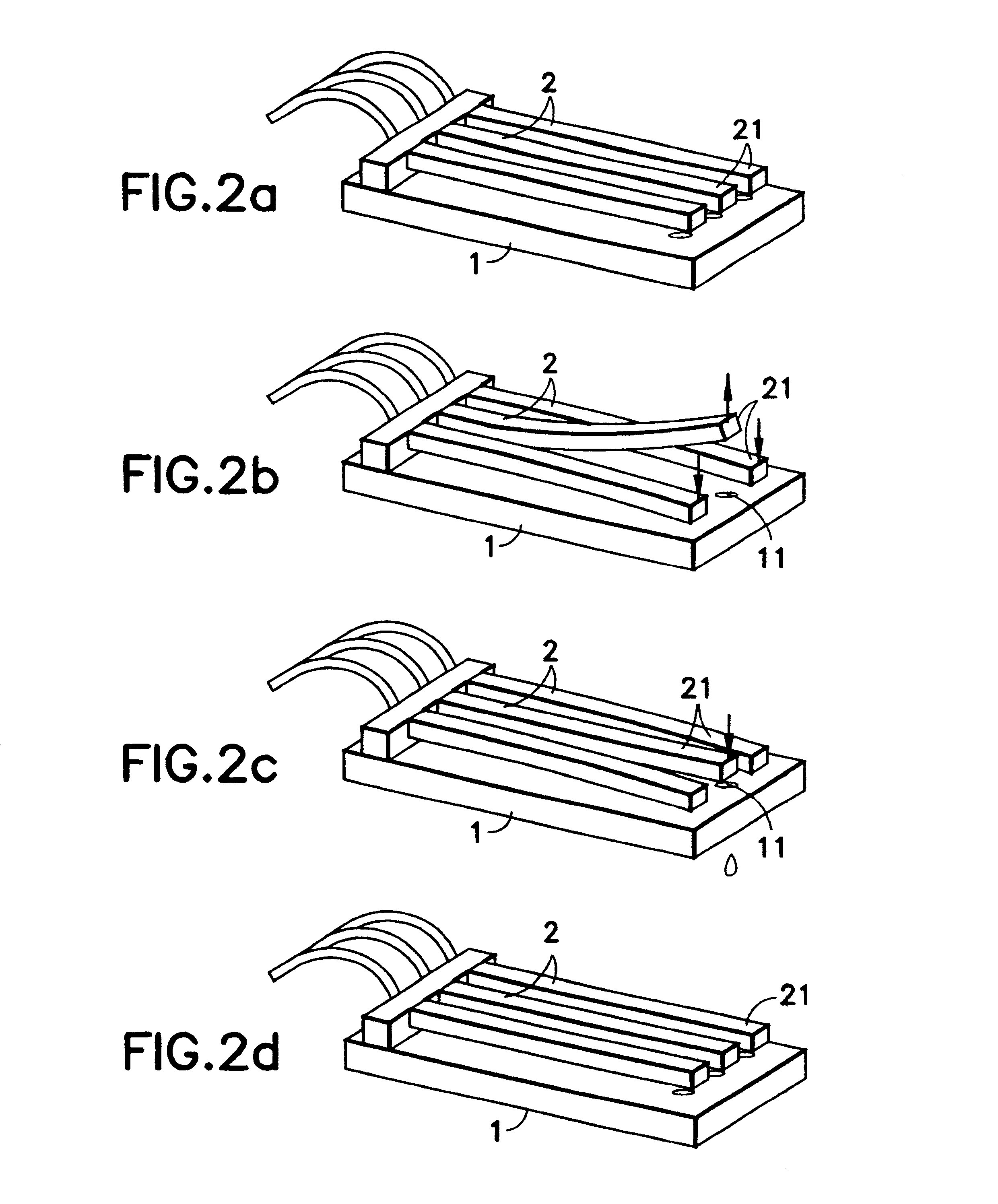
The principle of the method according to the invention is shown in FIGS. 1a to 1e. Each of the figures schematically shows a detail of a piezo bending transducer drop-on-demand print head. As shown, in a nozzle plate 1 has three nozzles 11 in series, extending perpendicularly to the plane of the plate. Parallel to the nozzle plate 1, three piezo bending transducers 2 are arranged in a series parallel next to one another in such a way that their non-restrained ends 21 are respectively opposite one of the nozzles 11. Each of the piezo bending transducers 2 can be bent about a bending axis extending parallel to the nozzle plate 1 and perpendicularly to the nozzles 11.

FIGS. 1a to 1e show the position of the three piezo bending transducers 2 in different stages of the sequence of movements which takes place by the middle of the three piezo bending transducers 2 being subjected to a triggering pulse.

In FIG. 1a, all three piezo bending transducers 2 are in the position of rest. In FIG. 1b,...


PUM


Abstract

Disclosed is a piezo bending transducer drop-on-demand print head and a method of actuating it. Each of the piezo bending transducers of a piezo bending transducer drop-on-demand print head is subjected to a sequence, corresponding to the desired print image, of triggering pulses each effecting a drop discharge movement and, assigned to each triggering pulse, each piezo bending transducer neighboring the piezo bending transducer triggered by the triggering pulse is subjected to a compensating pulse deflecting it. The piezo bending transducer drop-on-demand print head has a nozzle plate with nozzles arranged in series. Respectively assigned to each nozzle is a piezo bending transducer which can be subjected to a triggering pulse accompanied by a drop being discharged from the respective nozzle. There is a control device by which each of the piezo bending transducers can be subjected to triggering pulses and compensating pulses in accordance with the method of the invention.

Description

1. Field of the InventionThe invention is in a drop-on-demand print head having a drop generator with nozzles arranged in series, respectively assigned to which there is a piezoelectric bending transducer for discharging sequences of drops and also is in a method of actuating a piezo bending transducer drop-on-demand print head.2. Description of the Related ArtA customary piezo bending transducer drop-on-demand print head is disclosed in DE 25 27 647 C3. A series of nozzles extending perpendicularly to the plane of a nozzle plate is provided in a plate of a head. Oriented parallel to the nozzle plate are piezo bending transducers in the form of an extending reed which is restrained at one end, so-called piezo reed transducers, arranged in a series adjacent and parallel to one another in such a way that their non-restrained ends are respectively opposite one of the nozzles. Each of the piezo bending transducers is designed as a piezo bimorph, which has a bending axis extending parall...

Claims


Application Information

Patent Timeline
IPC IPC(8): B41J2/14B41J2/045B41J2/055H01L41/09
CPCB41J2/04525B41J2/04581B41J2/04596B41J2/14282B41J2002/14354
Inventor HEINZL, JOACHIMEDERER, INGOSEITZ, HERMANN
Owner TALLY COMPDRUCKER
Learn More